
Implant

A technology of implants and connection plugs, which is applied in the field of implants, can solve the problems of fixing screws for a long time and time-consuming, and achieve the effects of simple and fast manufacturing and disconnection, low processing cost of grooves, and reduced use time

Inactive Publication Date: 2006-11-15
HERAEUS KULZER GMBH
View PDF1 Cites 0 Cited by
  • Summary
  • Abstract
  • Description
  • Claims
  • Application Information

AI Technical Summary

Problems solved by technology

But it also has a disadvantage, that is, it takes a long time to screw in the fixing screw, especially in the case of a large number of replacement teeth, it is often required that the connection between the medical component and the implant is only temporary, that is, the medical component is in a certain condition. Must be removed from implant after time
There is also the process of taking it out. In the case of this kind of screw connection, it takes time to unscrew the screw

Method used


Image

  • Implant
  • Implant
  • Implant

Examples


Embodiment Construction

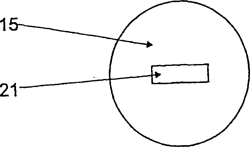
[0028] Figure 1 to Figure 5 It is an implant 1 made of titanium, which has an approximately conical shape with external threads 2 on its outer surface. The implant 1 also has a rounded distal end 3 and a proximal end 4, and the proximal end is composed of a true circular upper top surface 5. In a section 6 adjacent to the upper top surface 5, the implant 1 has a cylindrical shape with an outer surface 7 that is highly polished. In the following threaded section 8, the implant 1 is made tapered. Starting from the upper top surface 5, a receiving eyelet 10 extends along the longitudinal axis 9 parallel to the implant 1 and passes through the total length of the segment 6 and a part of the length of the threaded segment 8.

[0029] Such as image 3 As shown, the cross-section of the receiving eye 10 in the range of the segment 6 is all a rounded rectangular shape. Starting from the threaded section 8, the cross section of the receiving eyelet 10 gradually becomes smaller downwards. ...


PUM


Abstract

An implant ( 1 ) for mounting a connection pin ( 17 ) of a medical device shows a longitudinal axis ( 9 ), a distal end ( 3 ) and a proximal end ( 4 ), from which extends a mounting recess ( 10 ) for the connection pin ( 17 ) in the direction of the longitudinal axis ( 9 ) into the inside of the implant ( 1 ). The outer generated surface of the implant ( 1 ) can be connected in a non-positive or positive manner with the inner generated surface of a mounting hole in a bone of a human or animal body. The connection pin ( 17 ), which is adapted to the mounting recess ( 10 ), can be connected in a non-positive or positive manner with the inner generated surface of the mounting recess ( 10 ). In order to enable rapid creation and similarly rapid breaking of the connection between the medical device and the implant ( 1 ), it is proposed that the inner generated surface of the mounting recess ( 10 ) should be provided with at least one depression extending perpendicular to the longitudinal axis ( 9 ) of the implant ( 1 ) and constituting an undercut, with which an outwardly protruding projection ( 20 a) of an elastic clip device ( 20 ) of the connection pin ( 17 ) can be radially engaged.

Description

Technical field [0001] The present invention relates to an implant for receiving a connecting plug of a medical element. The implant has a longitudinal axis, a distal end and a proximal end. The proximal end has a receiving eye for receiving the connecting plug extending along the longitudinal axis. Inside the implant, the implant can be forced or elastically locked to connect the inner surface of the receiving hole in the bone of the human or animal body with the outer surface of the implant, and at the same time match the receiving eye The connecting plug (17) can also be connected with the inner surface of the receiving eyelet by means of force or elastic locking. Background technique [0002] This type of implant system has become very popular in the dental field, for example. In this case, the medical element to be received can be a replacement tooth, a closure cap, a mold post or a gingival former. The replacement tooth published in WO 99 / 29255 is composed of a connecting p...

Claims


Application Information

Patent Timeline
Patent Type & Authority Patents(China)
IPC IPC(8): A61C8/00A61B17/68A61F2/30A61F2/02A61F2/00
CPCA61C8/005A61C8/0065A61C8/0066A61C8/0069A61C8/0071A61F2002/30359A61F2220/0033A61C8/008A61C13/0001A61C8/0062
Inventor 米夏埃尔·奥古森曼弗雷德·彼得斯克劳斯·哈泽尔胡恩胡贝图斯·施皮克曼
Owner HERAEUS KULZER GMBH
Learn More