Liquid ejecting out device and its driving method

A driving method and technology of liquid nozzles, applied in printing and other directions, can solve the problems of easy entrainment of the meniscus, damage to the shape of the meniscus, and unstable ejection characteristics.

Inactive Publication Date: 2006-07-05
SEIKO EPSON CORP
View PDF0 Cites 0 Cited by
  • Summary
  • Abstract
  • Description
  • Claims
  • Application Information

AI Technical Summary

Problems solved by technology

If flushing is performed with a large dot in the state where fine air bubbles remain in the nozzle opening, the meniscus is easily drawn into the meniscus because the meniscus is pulled in a large amount when flushing with a large dot. The involvement of residual air bubbles can easily lead to the destruction of the meniscus
Also, since the shape of the meniscus after cleaning is somewhat damaged, when a high-frequency drive signal is used, the ejection characteristics during flushing become unstable, which may also cause the meniscus to be damaged.

Method used


Image

  • Liquid ejecting out device and its driving method
  • Liquid ejecting out device and its driving method
  • Liquid ejecting out device and its driving method

Examples


Embodiment Construction

[0059] Embodiments of the present invention will be described below with reference to the drawings.

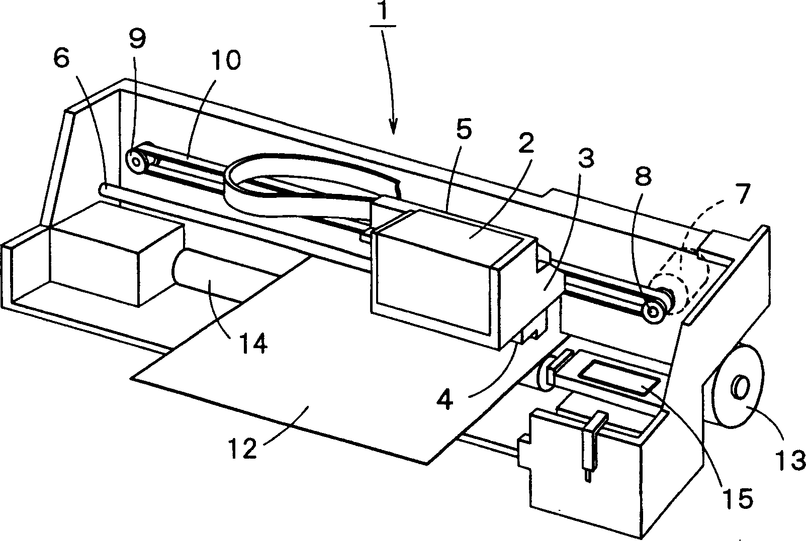
[0060] Such as figure 1 As shown, the inkjet recording device of this embodiment is an inkjet printer 1 including a carriage 5 having an ink cartridge holder 3 capable of holding an ink cartridge 2 and a recording head 4 (liquid ejection head). The carriage 5 is driven by the scanning mechanism to reciprocate along the main scanning direction.

[0061] The head scanning mechanism is composed of the following parts: a guide member 6 erected on the left and right direction of the casing; a pulse motor 7 erected on one side of the casing; a drive pulley 8 connected to the rotating shaft of the pulse motor 7 and driven by rotation; The driven pulley 9 that is installed in the other side of casing; Hang between driving pulley 8 and driven pulley 9, and the timing belt 10 that combines with carriage 5; Figure 5 ). Thus, by operating the pulse motor 7, the carriage 5, that is, t...


PUM


Abstract

The liquid-jetting apparatus has a liquid-jetting head with nozzle openings through which liquid particles are jetted. The liquid-jetting head performs a flushing operation to remove the thickened liquid from the nozzle openings to recover its normal liquid-jetting ability. The flushing operation jets liquid particles having a weight of 10 ng or below successively through the nozzle openings at a jetting speed of 8 m / s or above. The liquid-jetting apparatus is capable of achieving a satisfactory flushing operation to ensure a satisfactory liquid-jetting characteristic by recovering from a thickened state in a liquid in the nozzle openings even if the liquid is un-uniformly thickened in the nozzle openings.

Description

technical field [0001] The present invention relates to a liquid ejection device having a liquid ejection head that ejects liquid droplets from nozzle openings and a driving method thereof. Background technique [0002] As a representative example of the liquid ejection device, there is an ink jet recording device such as an ink jet printer or a plotter. This inkjet recording device moves the recording head (liquid ejection head) along the main scanning direction, and moves the recording paper (a kind of printing recording medium) along the sub scanning direction, and by interlocking with this movement, the nozzles of the recording head Ink droplets are ejected from the openings to record images (characters) on recording paper. The ejection of ink droplets is performed, for example, by changing the ink pressure in a pressure chamber communicating with the nozzle opening. [0003] Ink pressure is varied by a pressure generating element such as a piezoelectric vibrator (piez...

Claims


Application Information

Patent Timeline
Patent Type & Authority Patents(China)
IPC IPC(8): B41J2/165
CPCB41J2/16526
Inventor 米洼周二张俊华松本圭次
Owner SEIKO EPSON CORP
Why Eureka
Try Eureka