
Plastic movable guide device for transmission

A transmission device and guide technology, applied in the direction of transmission device, belt/chain/gear, mechanical equipment, etc., can solve the problems of deformation of reinforcement plate, reduction of assembly capacity, increase of production cost, etc.

Inactive Publication Date: 2006-06-21
TSUBAKIMOTO CHAIN CO
View PDF0 Cites 0 Cited by
  • Summary
  • Abstract
  • Description
  • Claims
  • Application Information

AI Technical Summary

Problems solved by technology

Therefore, strengthening treatment such as heat treatment must be performed on the reinforcing plate in advance in order to improve the wear resistance of the reinforcing plate, which is one cause of an increase in production cost
In addition, since the reinforcing plate is subjected to strengthening treatment such as heat treatment, etc., the reinforcing plate is deformed, and it is understood that in this case, the ability to fit the reinforcing plate into the slit is reduced

Method used


Image

  • Plastic movable guide device for transmission
  • Plastic movable guide device for transmission
  • Plastic movable guide device for transmission

Examples


Embodiment Construction

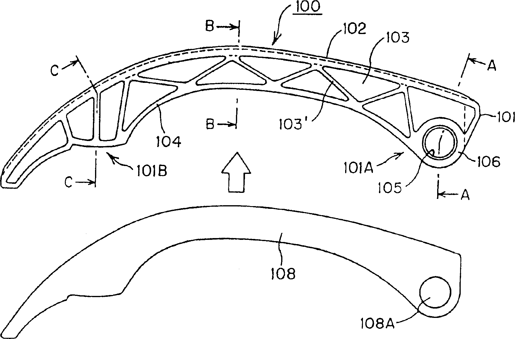
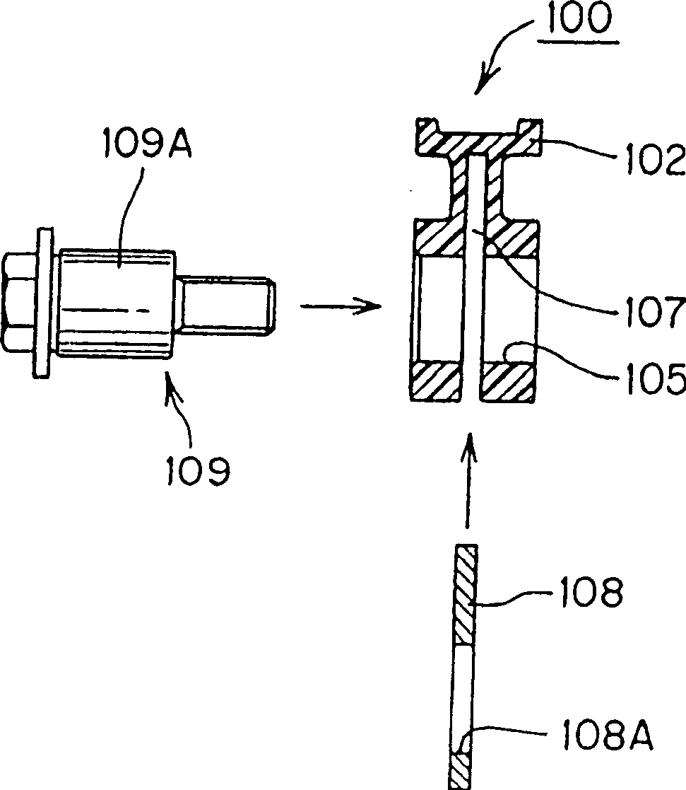
[0027] The following will refer to Figures 1 to 5 An embodiment of the present invention will be described. figure 1 The assembled state of a plastic movable guide 100 used in a chain drive is shown. The movable guide 100 is formed by inserting a reinforcing plate 108 into the guide main body 101 in the direction of the arrow. figure 2 yes figure 1 Bottom side plan view of the plastic movable guide shown. image 3 is along figure 1 Sectional view of midline A-A. Figure 4 is along figure 1 Sectional view of midline B-B. in addition, Figure 5 is a cross-sectional view along the line C-C, wherein the plunger 110 and the figure 1 The plunger receiving portion 101B on the pivoting front end side of the plastic movable guide is shown in contact.

[0028] This guide main body 101 is a plastic main body integrally molded from synthetic resin, includes a support pad portion 102 with a sliding surface that is in sliding contact with the running chain on one surface sid...


PUM


Abstract

The present invention provides a plastic movable guide having excellent noiselessness and assembling ability and capable of reducing production cost. On the pivoting front end side of the guide body 101, a plunger accommodating portion 101B, which a plunger of the tensioner can contact and press, is provided, and a reinforcing plate 108 is provided in a slightly recessed manner. The plunger receiving portion 108 is such that the reinforcing plate 108 does not protrude from the edge of the opening in the slit.

Description

technical field [0001] The present invention relates to a plastic movable guide for transmissions used by mounting them rotatably around an axis such as tension rods, slides, etc. , driven side sprockets and chains wound on these sprockets and circulated to transmit power from the driving side to the driven side transmission, or the movable guide is used to pass the driving side pulley, driven Side pulleys and a belt that circulates around these pulleys transmit power from the driving side to the driven side of the transmission. Background technique [0002] Engines, drives, etc. typically include transmissions that transmit power via chains, belts, etc. In such transmissions that have been used, a movable guide with a sliding function is provided, which can apply a suitable tension to the circulating chain or belt in sliding contact with it, and prevent vertical vibration and vibration of the running chain or belt. Lateral vibration. This movable guide is connected to th...

Claims


Application Information

Patent Timeline
IPC IPC(8): F16H7/18F16H7/08
CPCF16H7/18F16H2007/0872
Inventor 河野敦黑畑纯也小西达也
Owner TSUBAKIMOTO CHAIN CO
Learn More