
Printed circuit board assembly device

A technology for printed circuit boards and utensils, applied in the direction of printed circuit board sockets, mounting board safety devices, support structure installation, etc., can solve the problems of preventing component disassembly, increasing the difficulty of testing, time and cost, testing, etc.

Inactive Publication Date: 2006-04-19
ABB (SCHWEIZ) AG
View PDF0 Cites 0 Cited by
  • Summary
  • Abstract
  • Description
  • Claims
  • Application Information

AI Technical Summary

Problems solved by technology

In these cases, a major limitation is the extreme difficulty in controlling and securing the plate spacing with maximum precision
Furthermore, this method, like the one described above, does not provide a structure that is strong enough and has independent mechanical stability; therefore, even taking into account the difficulty of achieving precise mutual positioning of the plates, the necessary tests cannot be performed directly on the frame, but must The entire assembly is pre-inserted into the housing, which increases the difficulty, time and cost of testing
[0005] Moreover, the fact should not be overlooked that in the known type of methods the connection between the panels and the connectors, i.e. the supports of the panels such as pins or part of the separating In addition to even preventing the disassembly of parts, it also makes it basically impossible to recycle the device at the end of its useful life
[0006] Finally, existing methods of known type cannot use more than two boards simultaneously, significantly reducing the potential functionality of the device as a whole

Method used


Image

  • Printed circuit board assembly device
  • Printed circuit board assembly device
  • Printed circuit board assembly device

Examples


Embodiment Construction

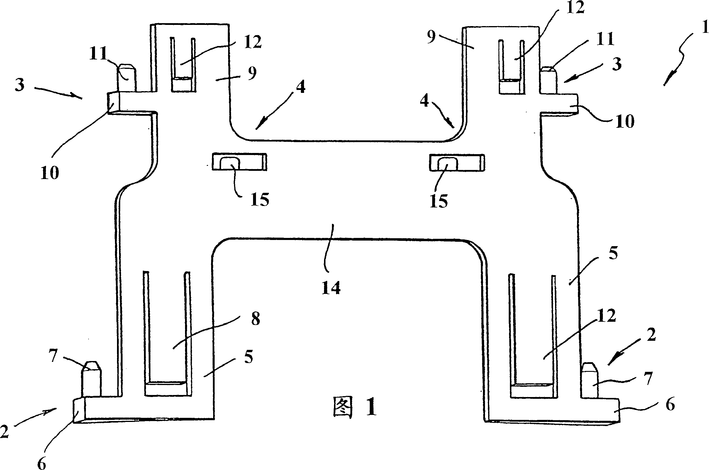
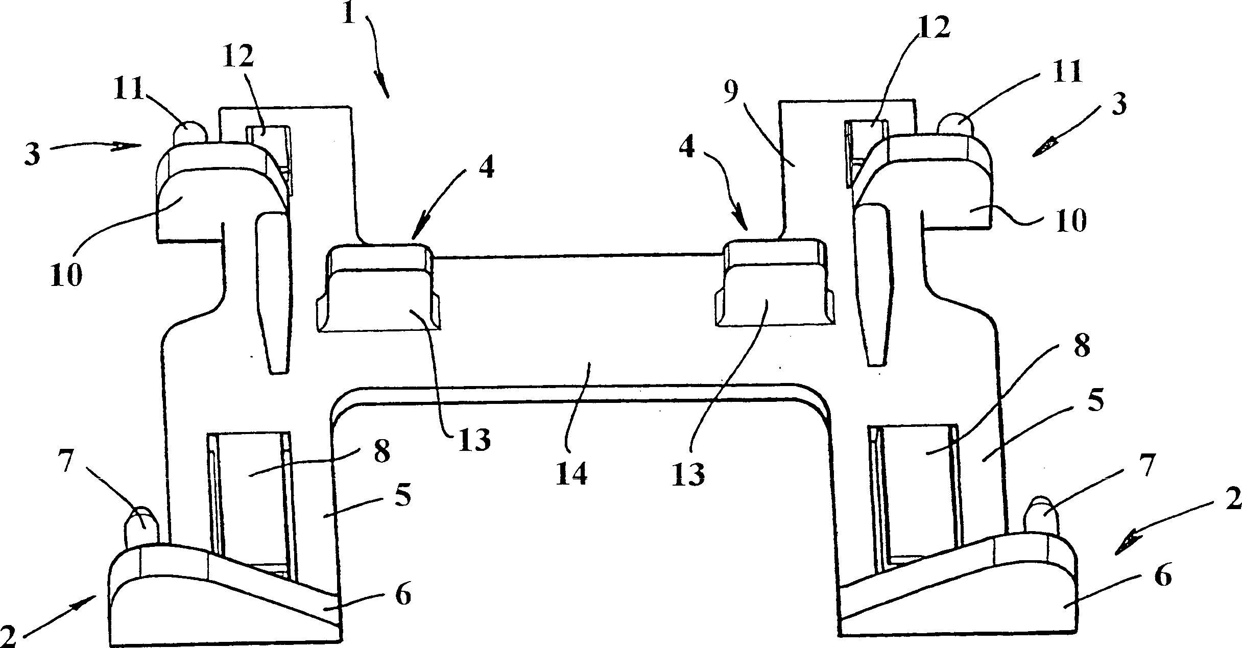
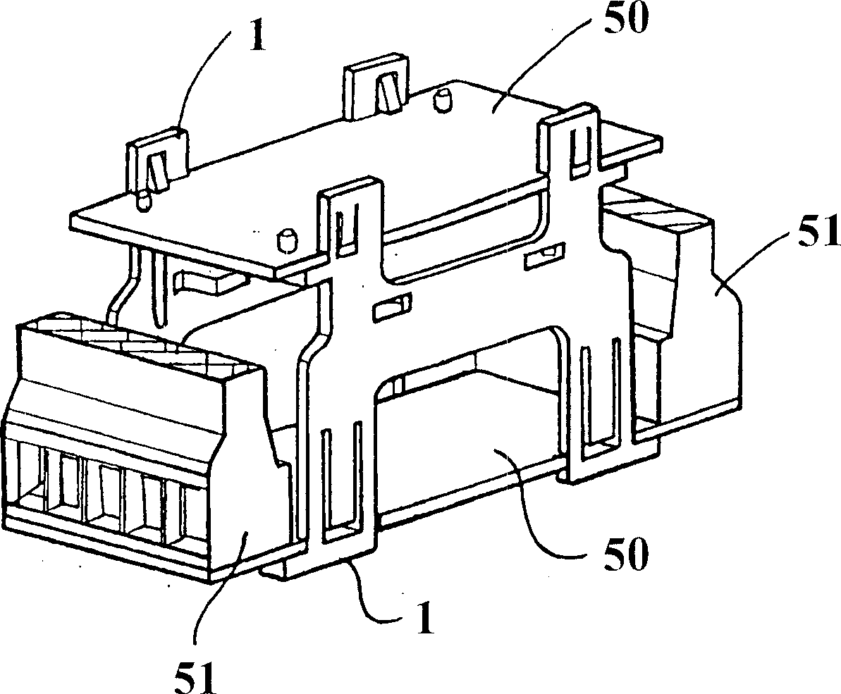
[0017] Referring to the above attached drawings, the image 3 and 4 The apparatus for assembling printed circuit boards according to the present invention represented by reference numeral 100 comprises a first support member and a second support member, both of which are represented by reference numeral 1 and adapted to be connected to at least two boards 50, so that the following Support the boards and connect them to each other in the manner explained in detail in the description above.

[0018] Advantageously, in the embodiment of the appliance according to the invention, the two supports 1 are substantially identical in structure, they are constructed according to a method of construction which reduces the number of molds required compared to methods of known type The necessary structural parts are produced and thus have the advantage of being advantageous from a cost and production point of view.

[0019] In particular, as shown in Figures 1 and 2, the support 1 has a fl...


PUM


Abstract

A device for assembling printed circuit boards, whose particularity consists of the fact that it comprises a first supporting element and a second supporting element that have a substantially flat body, from one face of which first and second coupling means protrude transversely for coupling, respectively, to at least one first board and one second board, the first and second supporting elements being suitable to be arranged along two corresponding edges of the first and second boards and to be coupled to them so as to support them and stack them in a mutually spaced arrangement, the first and second supporting elements being structurally substantially identical to each other.

Description

technical field [0001] The present invention relates to a printed circuit board assembly tool with improved function and performance. Background technique [0002] It is known that some modular electronic devices, such as timers, employ suitable boards on which electronic circuits are printed and on which are mounted the various components required to use the device. In particular, currently available modular units typically employ two boards that fit together according to various construction methods, thereby providing a frame in which the boards are spaced apart from each other and providing space for the various devices mounted on the board space; the resulting assembly is then inserted into the device housing. [0003] In the background art, the method of fitting panels to each other and using them in a device has several drawbacks and disadvantages. In particular, the first method of construction employs two supports positioned along both sides of the plate and shaped...

Claims


Application Information

Patent Timeline
IPC IPC(8): H05K7/14
CPCH05K7/1417H05K7/1428
Inventor C·莫尔拉基A·卡雷托尼
Owner ABB (SCHWEIZ) AG
Learn More