Re-Configuration in digital network

A technology of reconfiguration and digital network, applied in the direction of data reset device, digital transmission system, data exchange network, etc., can solve problems such as inappropriate long time

Inactive Publication Date: 2006-04-19
KONINKLIJKE PHILIPS ELECTRONICS NV
View PDF1 Cites 0 Cited by
  • Summary
  • Abstract
  • Description
  • Claims
  • Application Information

AI Technical Summary

Problems solved by technology

In some circumstances this may take an unduly long time, where the reason is that some stations may need to exchange large amounts of information with one or more other stations, and / or some stations may be characterized by: a large amount of inherent delay before they will be fully operational again

Method used


Image

  • Re-Configuration in digital network
  • Re-Configuration in digital network
  • Re-Configuration in digital network

Examples


Embodiment Construction

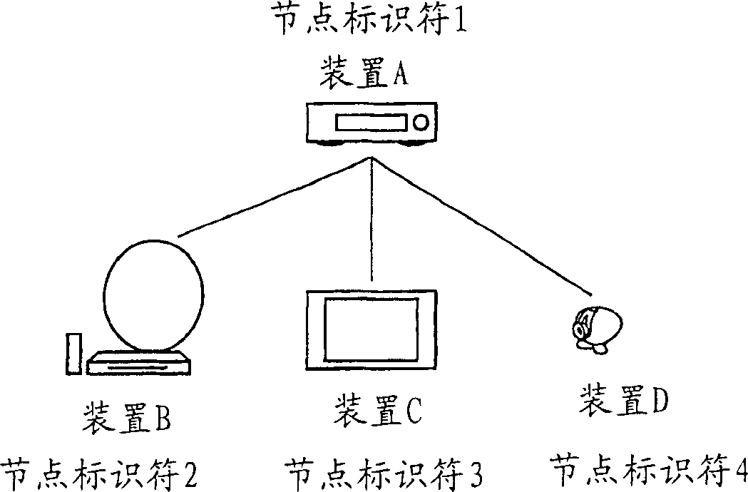
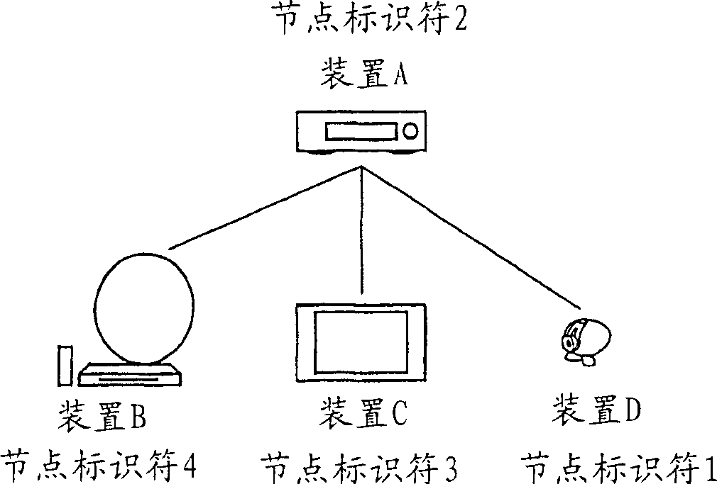
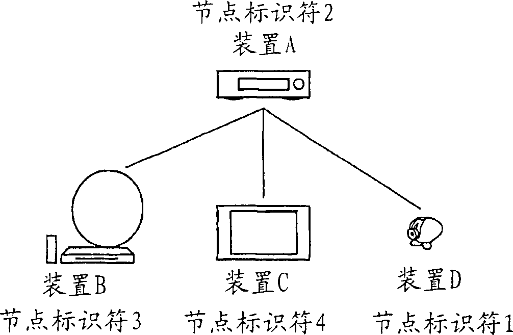
[0016] A digital network (such as, but not limited to, a home network) typically consists of a set of nodes interconnected by point-to-point physical links. The nodes may represent various user functional devices, such as audio and / or video components, security cameras, home appliances, antenna dishes or other external link stations, as well as system level devices such as subaltern networks. In response to an initial event such as a bus reset, the network will be reconfigured and a new logical view of the entire state of the network must be created. For each node, this logical view or topology map will contain the corresponding node itself, its interconnections, and such additional functionality or other information for the corresponding node as appropriate. Other nodes will collect this additional information for each specific node based on the identifier of the specific logical node. Following reconfiguration, one or more nodes will store the total logical view of the netw...


PUM


Abstract

A method for executing a re-configuration in a self-configuring digital network after occurrence of a reconfiguration trigger, through upon detecting such trigger, communicating between various physical nodes their respective logical node identifiers and furthermore functionality informations regarding the respective node stations, said method being characterized by, associated to such detecting, recognizing in a particular node such other nodes that are conducting a communication relation with said particular node, marking all logical node mappings on the various physical nodes as invalid, through said communicating of logical node identifiers establishing said reconfiguration, whilst executing communicating said functionality informations on a basis of necessity.

Description

technical field [0001] The invention relates to a method for performing reconfiguration in a self-configuring digital network when a reconfiguration trigger occurs. A non-limiting example of such a network is the serial bus network IEEE 1394-1995 as discussed in International PCT Patent Application WO00 / 23869. The standard allows for a plug-and-play capability, and although it was originally intended for computer-based applications, it has also been introduced into indoor consumer electronics networks. Its basic definition level is the physical level. Various modifications and extensions to this standard have been implemented in Standards 1394A2000 and P1394.1. Another possible implementation of the invention is the USB bus standard. Background technique [0002] The above mentioned standards have been combined with the HAVI or Home Audio / Video Interoperability principles operating at a conceptual level. This allows the controlling device or node to be combined with the ...

Claims


Application Information

Patent Timeline
IPC IPC(8): H04L12/28H04L12/64H04N7/24G06F1/24G06F13/42H04L29/14H04L29/12G06F13/14G06F13/38H04L12/40H04L69/40
CPCH04N21/43615H04L12/2805H04L29/12594H04L12/6418H04L29/12254H04L12/2807H04L61/10H04L61/2038H04L61/3005H04L29/1232H04L29/12018H04L12/40078H04L12/40117H04L29/12301H04L61/2092H04L61/2076H04L61/5076H04L61/5038H04L61/5092H04L61/30H04L12/40
Inventor D·范德莫伊伦霍夫
Owner KONINKLIJKE PHILIPS ELECTRONICS NV
Why Eureka
Try Eureka