Method for controlling reluctance motor rotor alignment and driving circuit for realizing the method thereof

A motor and rotor technology, applied in the field of the invention involving a switched reluctance motor, can solve problems such as strong noise

Inactive Publication Date: 2006-04-12
LG ELECTRONICS INC
View PDF0 Cites 1 Cited by
  • Summary
  • Abstract
  • Description
  • Claims
  • Application Information

AI Technical Summary

Problems solved by technology

Furthermore, such a large current produces strong noise when each pair of rotor salient pol...

Method used


Image

  • Method for controlling reluctance motor rotor alignment and driving circuit for realizing the method thereof
  • Method for controlling reluctance motor rotor alignment and driving circuit for realizing the method thereof
  • Method for controlling reluctance motor rotor alignment and driving circuit for realizing the method thereof

Examples


Embodiment Construction

[0028] Preferred embodiments of the present invention will be described in detail below with reference to the accompanying drawings.

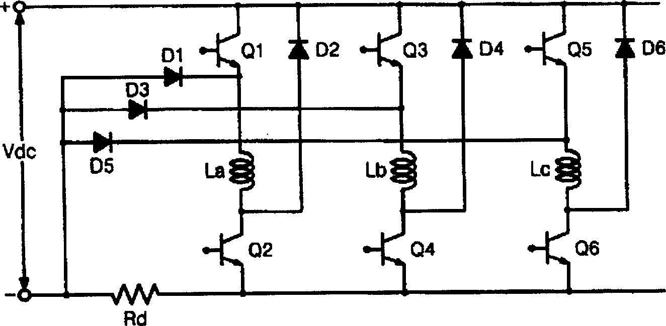
[0029] image 3 is a schematic circuit diagram representing an SRM structure according to the present invention;

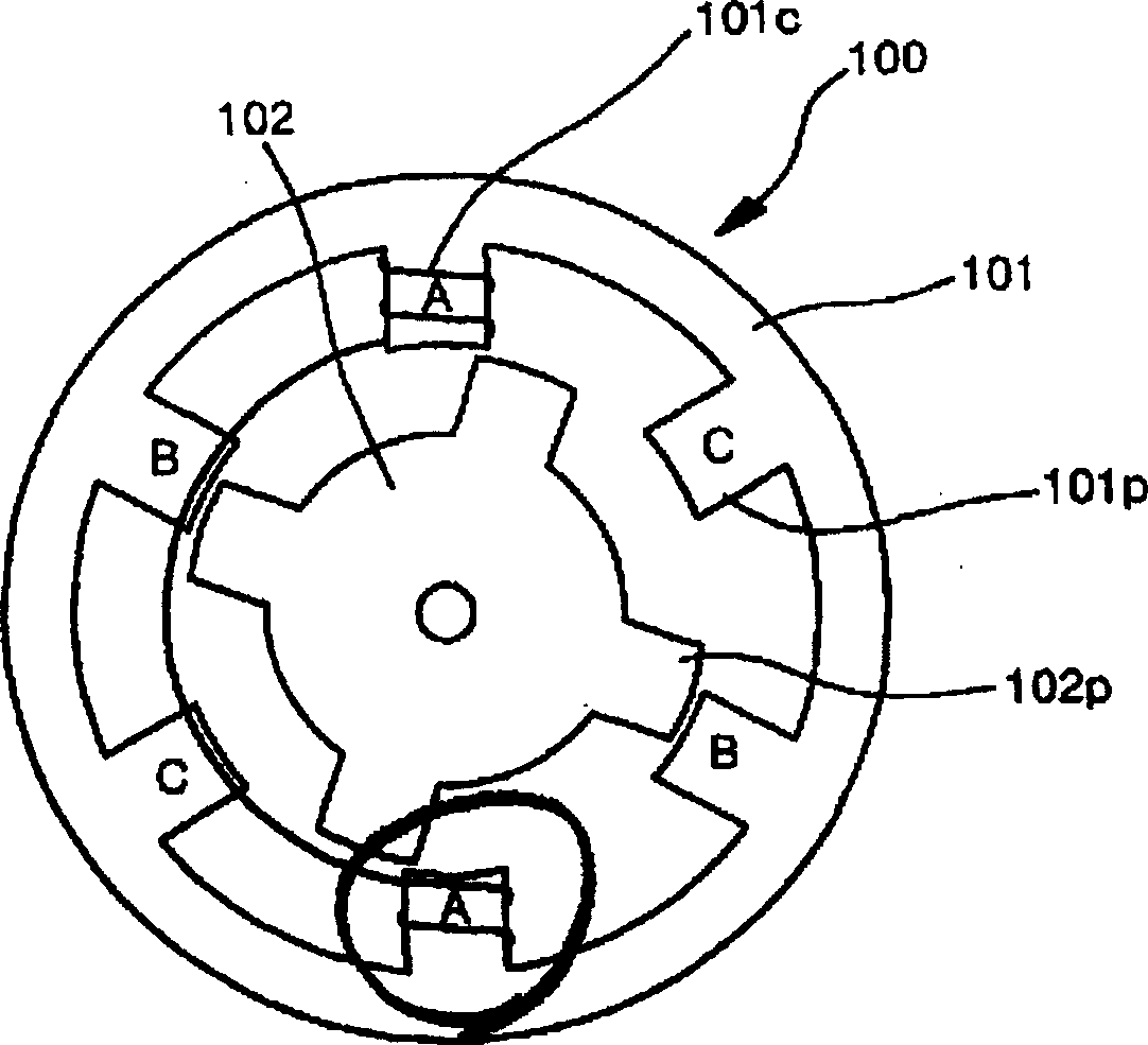
[0030] refer to image 3 , according to the SRM 100 of the present invention (see figure 1) includes: a stator, which has a plurality of radially inwardly extending stator poles 101p, which are formed according to a plurality of pairs of stator salient poles A-A, B-B, and C-C diametrically opposed, and a phase coil is wound around each stator salient pole (that is, around windings of any two diametrically opposed salient poles of the stator, connected in series or in parallel to define a phase of the motor) 101c; and a rotor 102 arranged around the rotating shaft inside the stator 101 and having a plurality of rotor poles extending radially outward 102p, which are formed in pairs of diametrically opposed rotor salient poles. Th...


PUM


Abstract

Disclosed is a method of controlling alignment of a rotor of an SRM with respect to a stator, the SRM including a stator having a plurality of diametrically opposed stator salient magnetic pole pairs around each which each of a plurality of phase coils is wound, and a rotor disposed about a shaft within the stator and having a plurality of diametrically opposed rotor salient pole pairs, comprising the steps of: applying a voltage pulse having an identical magnitude to each phase coil surrounding the plurality of pairs of stator salient magnetic poles in a plurality of respective motor phases of a stator of the SRM upon the initial starting of the SRM; detecting current flowing into the each phase coil in the plurality of respective motor phases in accordance to the application of the voltage pulse; comparing the respective magnitude values of the detected current in the respective motor phases with each other; and (d) bringing rotor salient pole pair of the rotor into alignment with a corresponding pair of stator salient poles of a motor phase with a phase coil into which current of the lowest level flows with the result of the comparison.

Description

technical field [0001] The present invention relates to a switched reluctance motor (hereinafter referred to as "SRM"), and more particularly to a method of controlling the alignment of the SRM's rotor relative to the stator, wherein, upon start-up of the SRM, an inflow around the SRM is detected. The currents of the phase coils of each pair of salient poles of the stator in the corresponding motor phases of the stator, so that the magnitudes of the sensed currents are compared with each other, so that the alignment of the rotor relative to the stator is controlled in such a way that a part of the rotor Alignment is achieved for a pair of stator salient poles corresponding to a motor-specific salient rotor pole, where the lowest level of current flows into the phase coils of the stator salient pole, thereby shortening the start-up time of the SRM and reducing the rotor relative to the stator start-up Noise generated during alignment. Background technique [0002] A synchron...

Claims


Application Information

Patent Timeline
IPC IPC(8): H02P6/00H02P1/16H02P6/06H02P6/08H02P25/08
CPCH02P1/163H02P6/22
Inventor 金相永
Owner LG ELECTRONICS INC
Why Eureka
Try Eureka