Filtering and flow-stabilizing device

A ballast and filter technology, applied in the field of automatic water supply device manufacturing without towers and pools, can solve the problems of long lichen, rust in the water tank, and the structure and technology cannot be removed, so as to achieve less investment and realize the Stability and the effect of preventing water pollution

Inactive Publication Date: 2006-03-29
陈立信
View PDF0 Cites 0 Cited by
  • Summary
  • Abstract
  • Description
  • Claims
  • Application Information

AI Technical Summary

Problems solved by technology

[0002] At present, all kinds of water supply equipment are structurally and technically unable to remove pools, water tanks and tap water to connect to the grid, let alone achieve the effect of constant pressure, variable energy storage and energy-saving water supply
There is the biggest technical defect: use pools and tanks to store water, store the pressured tap water in the pool, and release the original pressure
Due to the rust of the water tank, red worms and moss growing in the pool, the secondary pollution of the water source is seriously caused, and the materials and electric energy are greatly wasted.

Method used


Image

  • Filtering and flow-stabilizing device
  • Filtering and flow-stabilizing device
  • Filtering and flow-stabilizing device

Examples


Embodiment 1

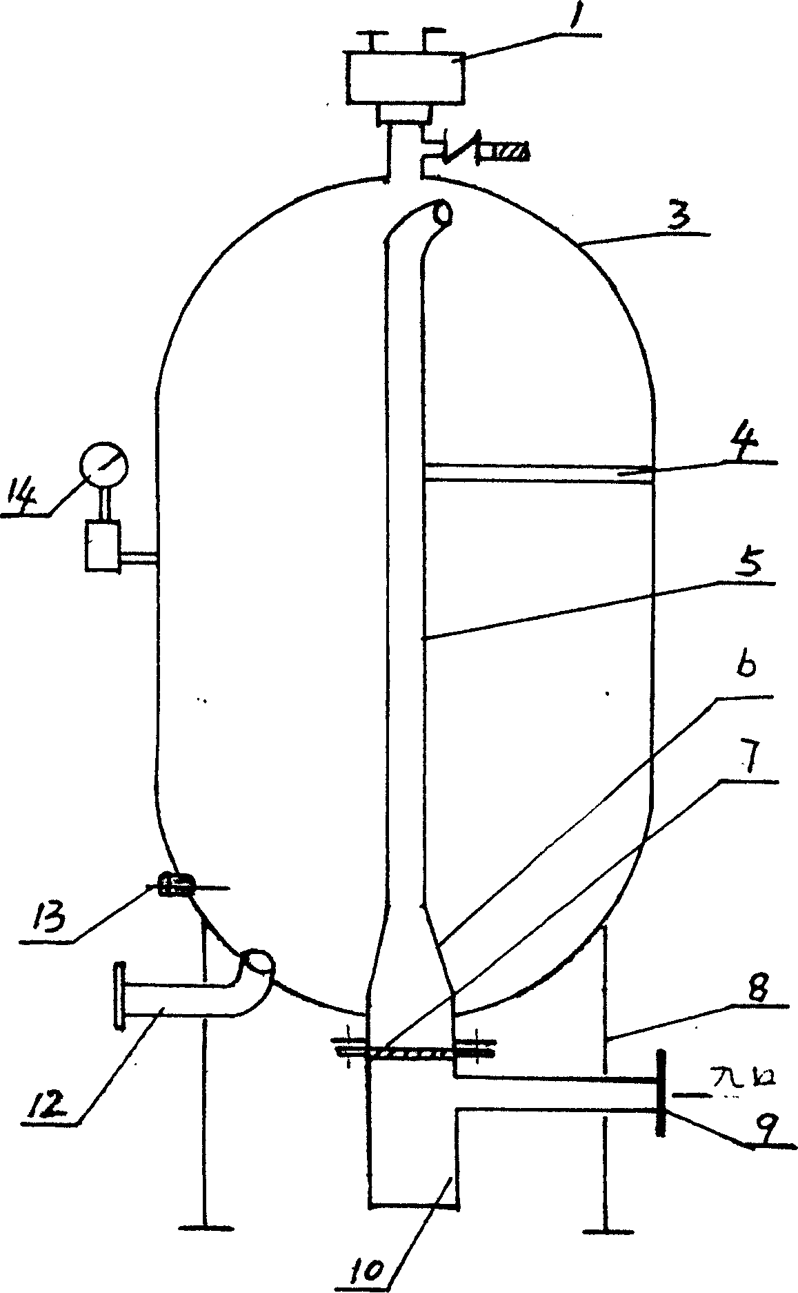
[0009] Embodiment 1: with reference to attached figure 1 . Filter ballast, which includes a controller, the cone reducing tube 6 is located in the ballast body 3, the cone reducing tube 6 communicates with the upper part of the filter body 10, the filter screen 7 is located in the filter body, and the water inlet 9 Connected to the filter body. One end of the guide tube 5 communicates with the tapered reducing tube 6 , and the other port is located in the ballast body 3 , and the guide tube 5 is fixed in the ballast body by the fixing bracket 4 . One end of the water outlet 12 is connected to the bottom of the ballast body, and the other end is connected to one or more water supply pipes in the motor pump water supply assembly. The upper end of the ballast body is provided with an automatic air intake and exhaust valve 1 . The lower part of the ballast body is provided with a water detection electrode 13, and its detection signal is sent to the frequency conversion soft star...

Embodiment 2

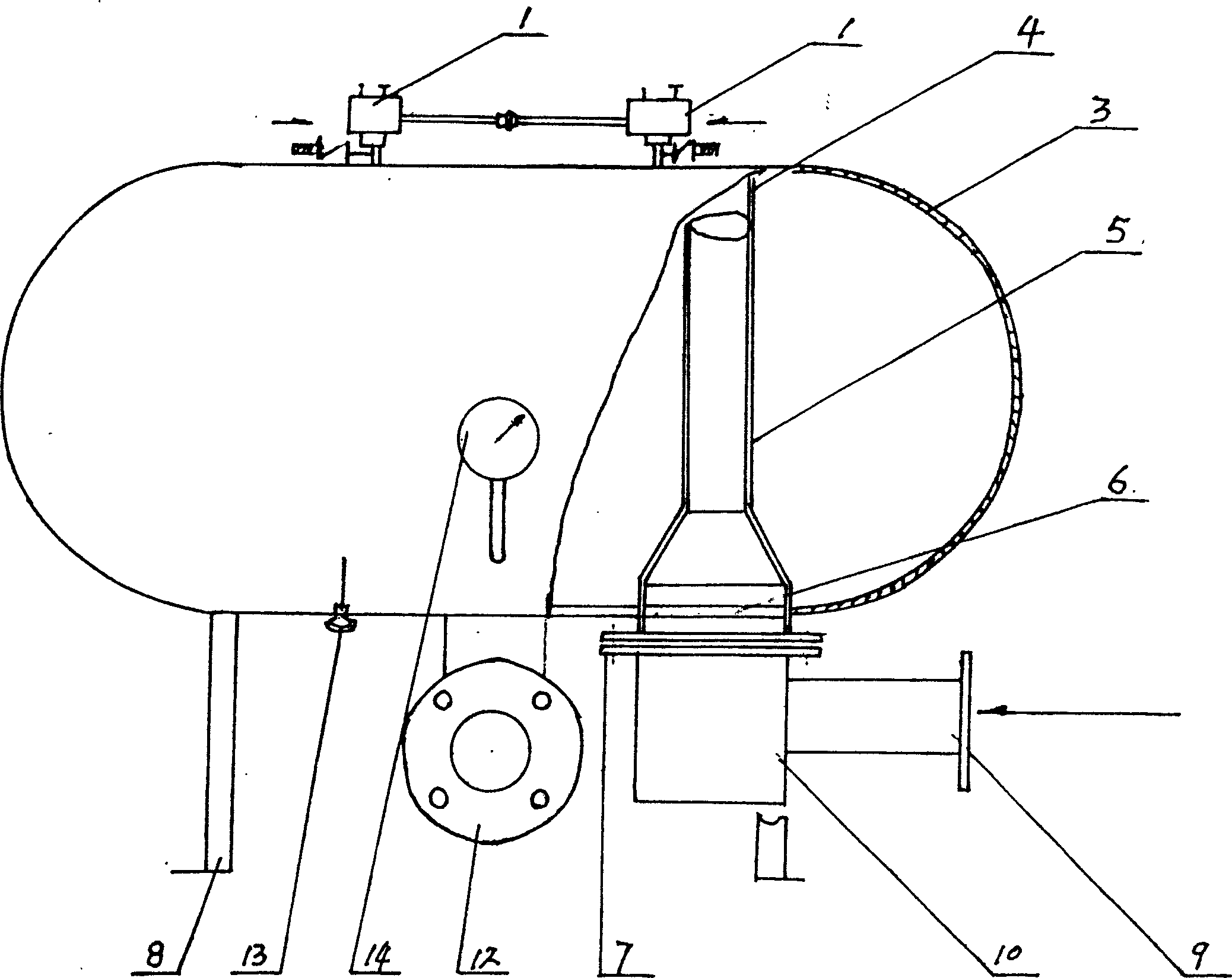
[0010] Embodiment 2: with reference to attached figure 2 . On the basis of Embodiment 1, the ballast body is in a horizontal structure.

Embodiment 3

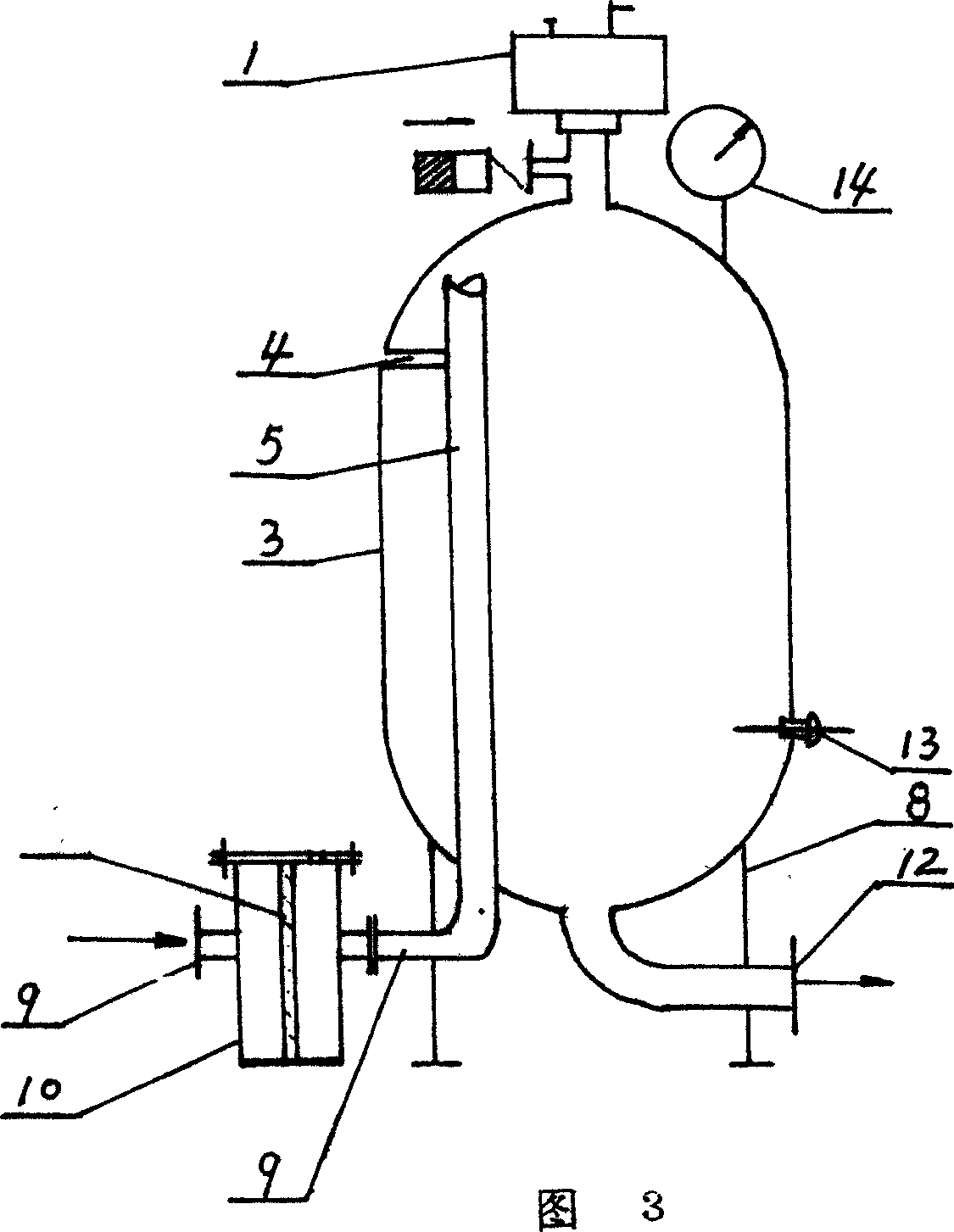
[0011] Embodiment 3: with reference to accompanying drawing 3. On the basis of Embodiment 1, the filter body 10 communicates with the guide pipe 5 through a connecting pipe.


PUM


Abstract

The filtering and flow-stabilizing device as one normal pressure container is used to replace available water reservoir and water tank. It has an diameter variable conic pipe inside the main body, a guide pipe with one end connected to the conic pipe and the other end inside the main body, a water outlet in the bottom and connected to one or several water supply assemblies with motor pump, an automatic air intake and exhaust valve, and a water source electrode in the bottom with detection signal fed to frequency variable soft starter. The present invention has the advantages of no need of building water reservoir causing secondary pollution of water; simple structure, high reliability and sealed steel structure without pollution and noise.

Description

Technical field: [0001] The invention relates to a non-negative pressure container, which is mainly used to replace water storage pools and water tanks, and belongs to the field of manufacturing automatic water supply devices without towers and pools. Background technique: [0002] At present, all kinds of water supply equipment are structurally and technically unable to remove pools, water tanks and tap water to connect to the grid, let alone achieve the effect of constant pressure, variable energy storage and energy-saving water supply. There is the biggest technical defect: adopt pond, water tank to store water, the tap with pressure is stored in the water storage pond, and original pressure is lost and released. In order to store water, the cost of building ponds and water tanks has been increased. Due to the rusting of the water tank, red worms and moss growing in the pool, secondary pollution of the water source is seriously caused, and materials and electric energy a...

Claims


Application Information

Patent Timeline
Patent Type & Authority Patents(China)
IPC IPC(8): E03B11/16
Inventor 陈立信
Owner 陈立信
Why Eureka
Try Eureka