Gas-solid cyclone fast separation device for lifting pipe

A swirl fast separation and riser technology, which is applied in chemical/physical processes, chemical instruments and methods, etc., can solve the problems of undiscovered literature and patent reports, and achieve the goals of avoiding overcracking reactions, efficient and rapid separation, and avoiding coking Effect

Inactive Publication Date: 2005-11-30
CHINA UNIV OF PETROLEUM (BEIJING)
View PDF21 Cites 1 Cited by
  • Summary
  • Abstract
  • Description
  • Claims
  • Application Information

AI Technical Summary

Problems solved by technology

However, the primary gas-solid separation efficiency of VSS and VQS cyclone fast separation equipment generally does not exceed 98-99%.
[0008] After domestic and foreign literature and patent searches, no literature and patent reports with the same main technical features as the present invention have been found

Method used


Image

  • Gas-solid cyclone fast separation device for lifting pipe
  • Gas-solid cyclone fast separation device for lifting pipe
  • Gas-solid cyclone fast separation device for lifting pipe

Examples


Embodiment 1

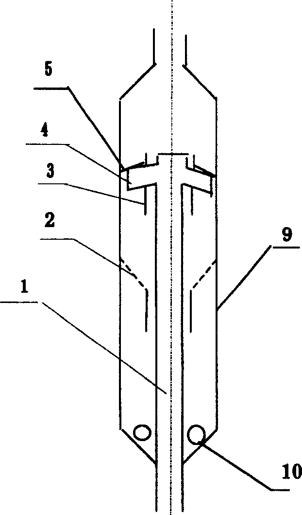
[0024] see figure 1 , in this embodiment, the riser (1) is placed inside the enclosure (9). The closing cover (9) is a cylindrical structure, and the inside of the closing cover (9) includes a riser (1), a conical stripping baffle (2), a splitter tube (3), a cyclone quick splitter (4), a splitter The baffle (5) and the stripper (10), the outlet end of the riser (1) is connected with the swirl quick splitter (4), and the splitter (3) is located at the outlet of the riser (1) and connected to the riser ( 1) Coaxial line, there is an annular channel between the outer wall of the outlet of the riser (1) and the inner wall of the splitter tube (3), and the multiple elbows (7) of the swirl quick splitter (4) respectively pass through the splitter tube (3) ), the outlet end of the elbow (7) is located in the space formed by the closure cover (9), the shunt cylinder (3) and the shunt baffle (5), and the shunt baffle (5) is placed in the swirl quick splitter ( 4) and welded on the inne...

Embodiment 2

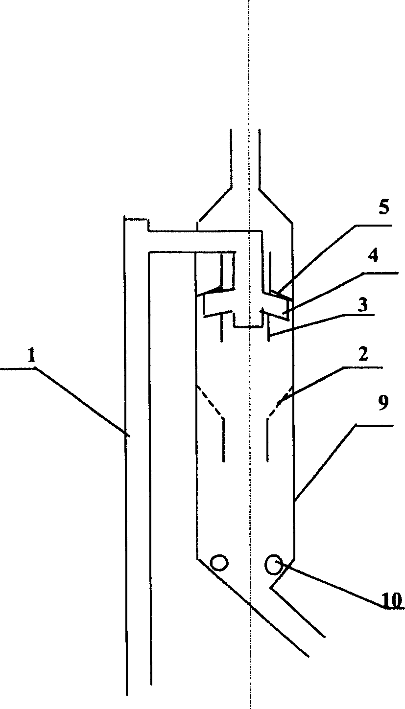
[0027] see figure 2 , in this embodiment, the riser (1) is placed outside the enclosure, and the upper part of the riser (1) turns above the diverter baffle (5), passes through the enclosure (9), and is placed downwards Inside the shunt cylinder (3). The closing cover (9) is a cylindrical structure, and the inside of the closing cover (9) includes a riser (1), a conical stripping baffle (2), a splitter tube (3), a cyclone quick splitter (4), a splitter The baffle (5) and the stripper (10), the outlet end of the riser (1) is connected with the swirl quick splitter (4), and the splitter (3) is located at the outlet of the riser (1) and connected to the riser ( The outlet of 1) is coaxial, and there is an annular channel between the outer wall of the outlet of the riser (1) and the inner wall of the splitter tube (3), and the multiple elbows (7) of the swirl quick splitter (4) respectively pass through the splitter The wall of the cylinder (3), the outlet end of the elbow (7) ...


PUM

PropertyMeasurementUnit
Apertureaaaaaaaaaa

Abstract

The present invention relates to cyclonic gas-solid separation apparatus and relates to the fast and efficient separation between the catalyst and oil gas in catalytically cracking riser tube reaction system. The apparatus includes riser tube, conic gas stripping baffle, separating tube, fast cyclonic separating head, separating baffle, gas stripping tube and closing hood. The fast cyclonic separating head consists of 3-5 downward tangential bending tubes. The auxiliary cyclone has closed top and side wall with several tangential slots. After the mixture of catalyst and oil gas is sprayed along bending tubes, the catalyst rotates and descends along the inner wall of the closed hood owing to the centrifugal force, while separated oil gas ascends along the separating tube, so as to realize the fast and efficient separation between gas and solid.

Description

technical field [0001] The invention belongs to the technical field of petrochemical industry, and relates to a fluidized catalytic cracking (FCC) riser reactor, in particular to a gas-solid cyclone fast separation device for a fluidized catalytic cracking (FCC) riser reactor. Background technique [0002] At the outlet of the riser of the fluidized catalytic cracking reaction system in the refinery, a gas-solid rapid separation device is installed to realize the separation of catalyst and oil and gas, and terminate unnecessary excessive reaction. There are currently two types of such separation devices. The first type is the inertial quick separation device, which relies on the gas-solid two-phase inertial difference generated when the oil and gas containing a large number of catalyst particles changes the flow direction sharply to achieve gas-solid separation. Typical inertial The rapid separation device has inverted L-type, T-type, multi-leaf type and other structures. Th...

Claims


Application Information

Patent Timeline
IPC IPC(8): B01J8/06
Inventor 卢春喜魏耀东时铭显
Owner CHINA UNIV OF PETROLEUM (BEIJING)
Why Eureka
Try Eureka