Light construction unit for on site pouring reinforced concrete filling

A reinforced concrete and cast-in-place technology, which is applied to building components, building structures, floor slabs, etc., can solve the problems of large hidden ribs, high material consumption, poor seismic performance, etc., and achieve improved strength and rigidity, and good integrity , the effect of high bonding strength

Inactive Publication Date: 2005-11-09
湖南邱则有专利战略策划有限公司
View PDF2 Cites 0 Cited by
  • Summary
  • Abstract
  • Description
  • Claims
  • Application Information

AI Technical Summary

Problems solved by technology

However, whether it is a hollow tube or a box, after it is applied to the cast-in-place concrete floor as a lightweight matrix, it will form a cast-in-place concrete hidden rib, and the size of the hidden rib is relatively large, and the material consumption is large, and the floor is heavy. , the seismic performance is correspondingly poor

Method used


Image

  • Light construction unit for on site pouring reinforced concrete filling
  • Light construction unit for on site pouring reinforced concrete filling
  • Light construction unit for on site pouring reinforced concrete filling

Examples


Embodiment Construction

[0051] The present invention will be further described below in conjunction with drawings and embodiments.

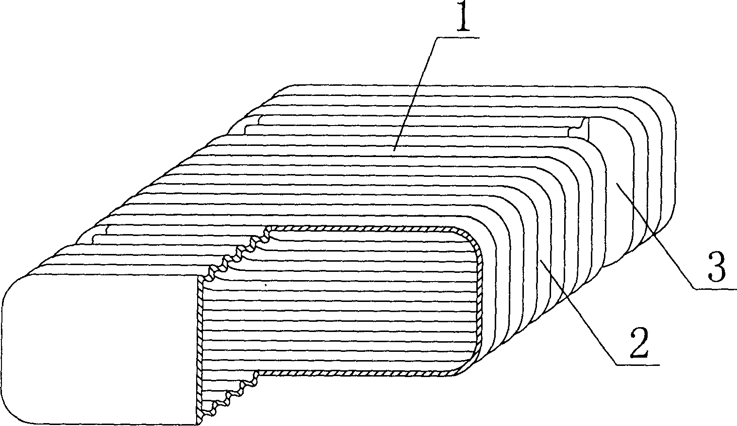
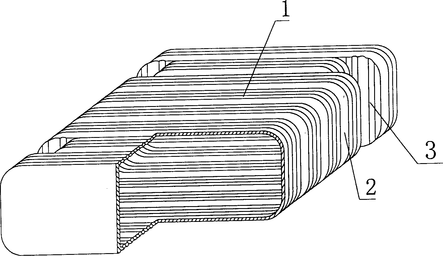
[0052] As shown in the drawings, the present invention includes a carcass 1, which is characterized in that the carcass 1 is a corrugated carcass, and at least one side 2 of the corrugated carcass 1 has at least one groove 3 running through the upper and lower surfaces. figure 1 It is a structural schematic diagram of Embodiment 1 of the present invention. figure 1 Among them, 1 is the corrugated carcass, 2 is the side of the corrugated carcass 1, and 3 is the groove. In the drawings, those with the same number have the same description. Such as figure 1 As shown, the carcass 1 is a corrugated carcass, and on the side 2 of the corrugated carcass 1 there are grooves 3 running through the upper and lower surfaces.

[0053] The present invention also lies in that the corrugations on the corrugated carcass 1 are positive corrugations, oblique corrugations, arc corrugation...


PUM


Abstract

A light filler member for in-situ casting concrete floor, roof, wall and foundation is a corrugated one with at least one slot on the side surface from top surface to bottom surface. When two such members are closely arranged, two adjacent slots can form a hole, in which the concrete can come in to form a post which can play the role of bearing and transferring the load, so greatly improving mechanical performance. Its advantages are light weight and low cost.

Description

(1) Technical field [0001] The invention relates to a lightweight component for filling cast-in-place reinforced concrete. (2) Background technology [0002] Beamless floor is currently the most widely used floor structure for cast-in-place concrete floors. It has the advantages of fast construction speed, small structural height, flexible division of indoor areas and no need for ceiling decoration. The lightweight permanent tire mold filled in it There are various hollow tubes and boxes, and the boxes are hollow or solid. For example, the patent No. ZL99232921.3, which the applicant applied for on March 10, 1999, is a utility model patent named "thin-walled tube for filling cast-in-place reinforced concrete", which consists of a hard thin-walled tube and two plugs. It is used as a lightweight permanent tire mold in beamless slabs. Another example is Liang Jun of Shijiazhuang City, Hebei Province. The patent No. ZL00203695.9 applied for on February 23, 2000, the formwork u...

Claims


Application Information

Patent Timeline
Patent Type & Authority Patents(China)
IPC IPC(8): E04B5/36
Inventor 邱则有
Owner 湖南邱则有专利战略策划有限公司
Why Eureka
Try Eureka