
Patsnap Eureka
For R&D, Patsnap Eureka makes reading and utilizing patents & technical documents easy.
Patsnap Eureka AIR
Designed for self-driven R&D workflows. Generate viable solutions, solve complex R&D challenges, empower your innovation with AI.

Patsnap Eureka Materials
Designed for material experts only. Revolutionize your material R&D, from search, analyze, to developing new materials.

TechResearch
Generate reliable direction feasibility study reports for your R&D in just a few steps.

TechSeek
Discover and master advanced knowledge NOW. Basics, ideas, possibilities, all at once.

TechMind
As an expert in R&D Theories, TechMind can generates customized viable solutions instantly.

TechRisk
Analyze your overall solution with one click, know your potential R&D risks in advance.

TechMonitor
Get weekly tech updates, stay abreast of the latest tech innovations and key insights.
Show case for cooling
A display cabinet, condenser technology, used in coolers, applications, home appliances, etc.
- Summary
- Abstract
- Description
- Claims
- Application Information
AI Technical Summary
Problems solved by technology
Method used
Image


Examples
Embodiment Construction
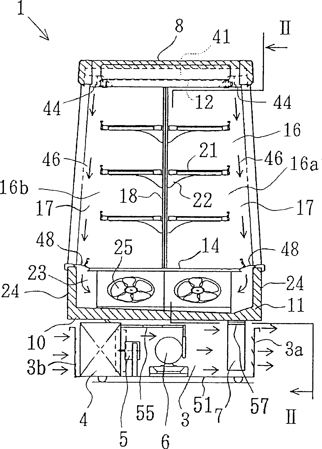
[0024] Embodiments of the display cabinet for cooling of the present invention will be described below in conjunction with the accompanying drawings.
[0025] First, a general description of cooling display cases. The machine room 3 is arranged in the lower part of the open display case 1 for refrigeration or freezing as a display case for cooling of various products such as soft drinks, lunch boxes, ham, and fruits. The machine room 3 is provided with a condenser 4, a condenser fan 5, a compressor 6, and a wiring box 7. The machine room 3 is provided with a first panel 3a on the front and a second panel 3b on the back. Ventilation openings are formed on the panels 3a, 3b, that is, the panels 3a, 3b are ventilation panels. Ventilation ports are also formed on the side plate 3 c of the machine room 3 .
[0026] The upper wall 8 of the display case 1, the side wall 9 on the right side, and the bottom wall 10 as the partition of the machine room 3 constitute an insulated box wi...
PUM
 Abstract
Description
Claims
Application Information
 - R&D Engineer
- R&D Manager
- IP Professional
- Industry Leading Data Capabilities
- Powerful AI technology
- Patent DNA Extraction
Browse by: Latest US Patents, China's latest patents, Technical Efficacy Thesaurus, Application Domain, Technology Topic, Popular Technical Reports.
© 2024 PatSnap. All rights reserved.Legal|Privacy policy|Modern Slavery Act Transparency Statement|Sitemap|About US| Contact US: help@patsnap.com