Method for producing an electromagnetic valve

A technology for solenoid valves and valve housings, applied in the direction of valve operation/release devices, valve details, multi-way valves, etc., to achieve uniform solder distribution, uniform high-quality brazing connections, and improved mechanical stability

Inactive Publication Date: 2005-07-20
哈拉尔德·施罗特
View PDF2 Cites 0 Cited by
  • Summary
  • Abstract
  • Description
  • Claims
  • Application Information

AI Technical Summary

Problems solved by technology

A problem with such valves is always the need for a permanent and stable connection of the connecting tube to the valve chamber or housing

Method used


Image

  • Method for producing an electromagnetic valve
  • Method for producing an electromagnetic valve

Examples


Embodiment Construction

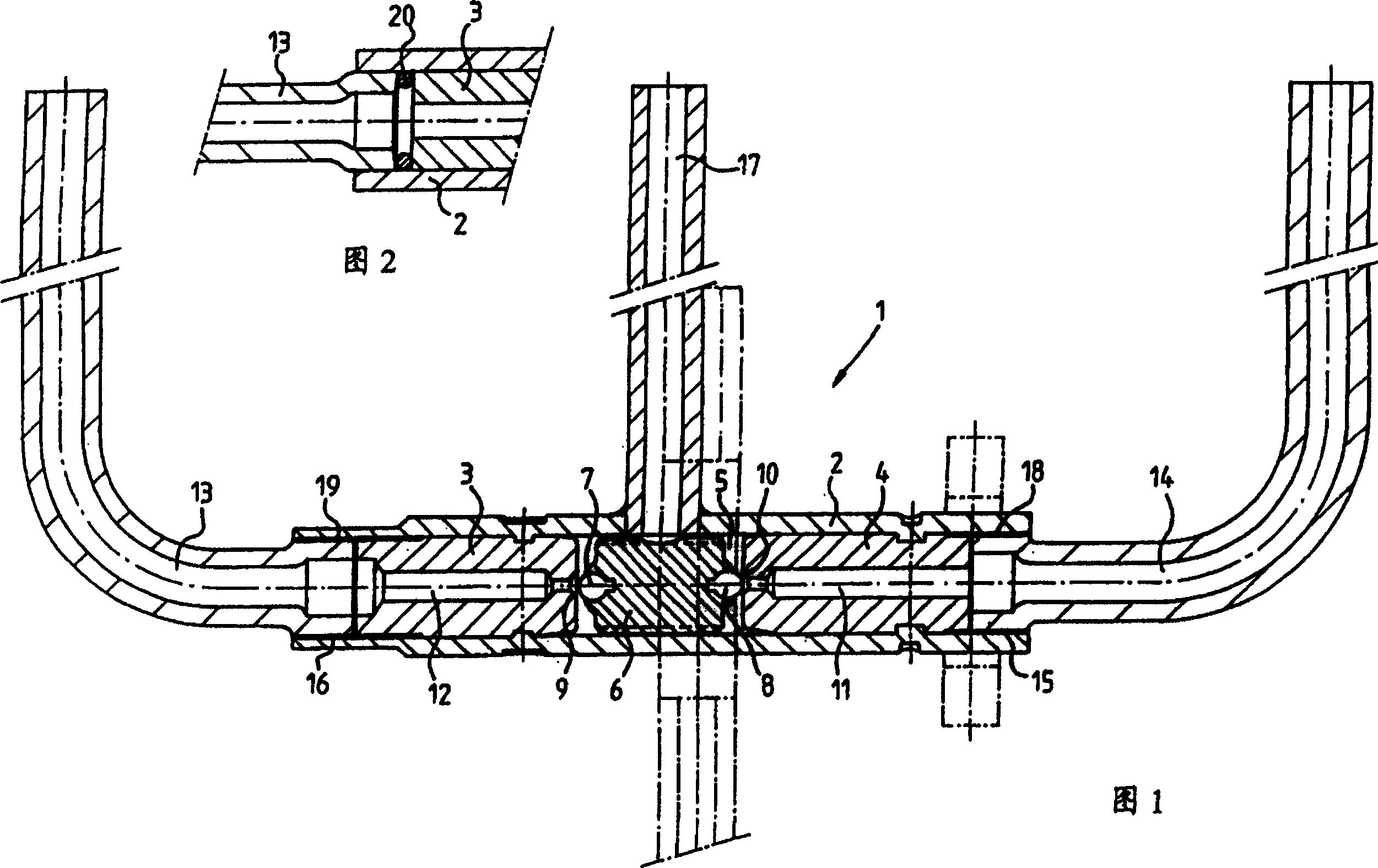
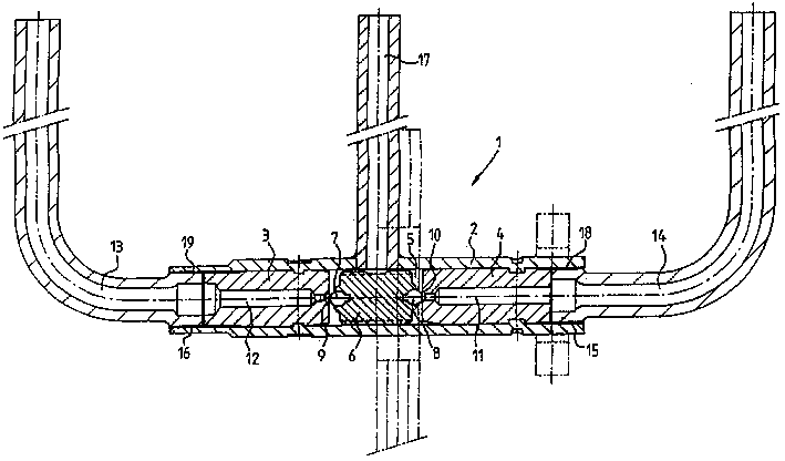
[0025] The valve 1 comprises a tubular valve housing 2 in which a valve chamber 5 is delimited by pole pieces 3 and 4 . A valve body 6 is movably mounted in the valve chamber 5 and can press two spherical seals 7 and 8 onto valve seats 9 and 10 fitted in the pole pieces 3 and 4 respectively.

[0026] The pole shoes 3 and 4 have connecting channels 11 and 12 which are connected to two connecting pipes 13 and 14 which are pushed into corresponding holes 15 and 16 in the valve housing 2 until they abut against the pole shoes 3 and 4 .

[0027] The valve 1 is used to switch the connection between the two connecting pipes 13 and 14 of a line 17 leading transversely into the valve chamber. In this way, the valve is bistable in any end position of the valve body 6 by means of a permanent magnet, not shown in detail, and can be actuated by a solenoid coil (also not shown in detail).

[0028] FIG. 1 shows the state after the brazed connection has been completed, wherein connecting pip...


PUM


Abstract

The invention relates to a method for producing an electromagnetic valve, especially one designed for circulating a coolant, whereby great tightness can be achieved in a simple manner. According to the invention, this is accomplished by soldering a joining pipe (13) to the valve housing (2) on the periphery side and to a pole shoe (3) mounted on the valve housing (2) on the face side.

Description

technical field [0001] The invention relates to a method for producing a solenoid valve and the solenoid valve. Background technique [0002] Printed publication DE 240 523 discloses a solenoid valve in which a lug inserted into the valve housing on the end side is soldered. [0003] High demands have been placed on the tightness and durability of solenoid valves, especially those used in coolant circuits of cooling units like refrigerators, freezers or the like. At the same time, however, it is desirable to produce such valves at the lowest possible cost, so that they can be produced economically in large quantities. [0004] A valve suitable for use in coolant circuits is disclosed, for example, in DE 37 184 90 . The valve has a valve housing in which is mounted a valve body movable in a valve chamber. A valve seat is formed in a pole shoe, which additionally has a channel connecting the valve chamber and a connecting pipe fastened to the valve housing. A problem with ...

Claims


Application Information

Patent Timeline
Patent Type & Authority Patents(China)
IPC IPC(8): F16K11/044F16K31/06F25B5/02
CPCF16K31/0606F25B5/02F16K31/0631F16K11/044F16K31/0627
Inventor 休伯特·奥特
Owner 哈拉尔德·施罗特
Why Eureka
Try Eureka