Method and apparatus for increasing detection rightness for contact-controllable detector

A correctness and detector technology, applied in the direction of instruments, signal transmission systems, character and pattern recognition, etc., to achieve the effect of reducing voltage difference or voltage gradient

Inactive Publication Date: 2005-03-16
ETURBOTOUCH TECH +1
View PDF1 Cites 0 Cited by
  • Summary
  • Abstract
  • Description
  • Claims
  • Application Information

AI Technical Summary

Problems solved by technology

[0007] The disadvantage of this case is that the conductive material is continuous, so when the corner contact is input with an appropriate voltage, the voltage drop ratio between each adjacent corner is quite large, and the voltage drop is reduced only by a single row of insulator regions and resistive electrodes. In other words, there will still be relatively large arc-shaped equipotential lines around the effective touch area of ​​the sensor, so that the action area needs to be a certain distance from the wiring area to avoid the arc-shaped equipotential effect. position shift phenomenon

Method used


Image

  • Method and apparatus for increasing detection rightness for contact-controllable detector
  • Method and apparatus for increasing detection rightness for contact-controllable detector
  • Method and apparatus for increasing detection rightness for contact-controllable detector

Examples


Embodiment Construction

[0032] The details and working conditions of the specific method proposed according to the present invention will be described in detail below in conjunction with the accompanying drawings.

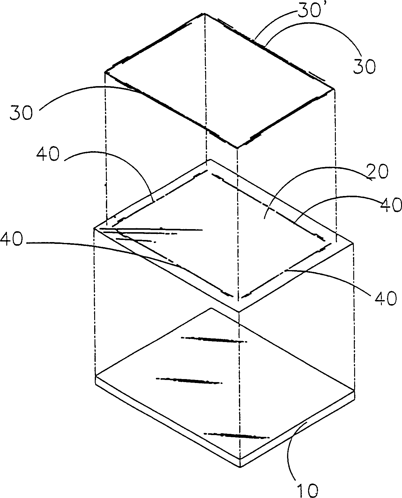
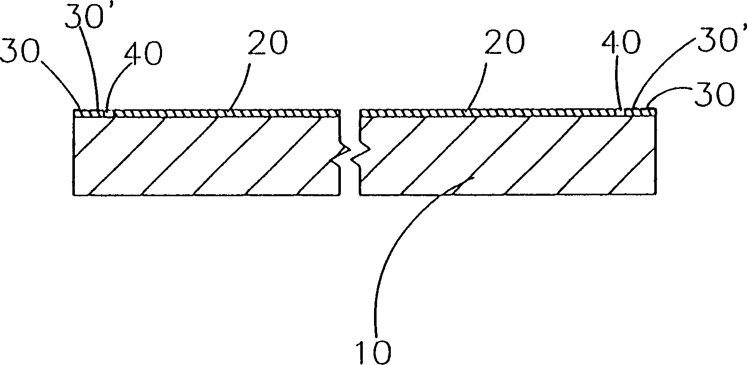
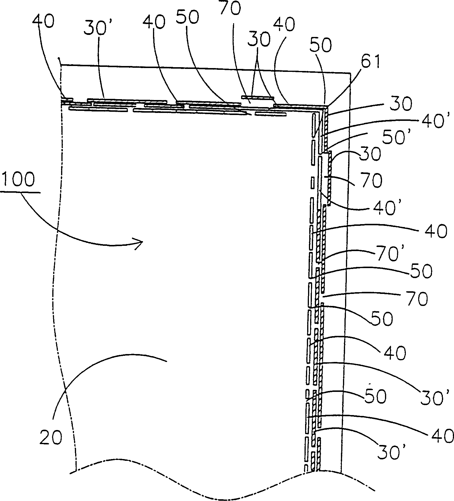
[0033] Please refer to the attached figure 1 , 2, shown in 3, the device of the present invention has substrate 10, wire, conductive film 20 and conductive material, it is characterized in that: a transparent or translucent substrate 10; Or printed on the upper surface of the substrate 10; a resistance element group 30 made of conductive material is printed on the periphery of the upper surface of the conductive film 20 in at least one row and in a discontinuous manner, wherein the independent The resistance element 30 is connected with the resistance element 30' and has wire contacts 61, 62, 63, 64, wherein each row of independent resistance elements 30 has a gap element 70; a conductive film 20 surface near the resistance element 30 inside , part of the conductive film 20 is deleted ...


PUM


Abstract

Discrete plural resistance elements are printed or coated on perimeter of electro-conductive film surface of the inductor. Gap components with different size are formed between each row of resistor element. Multiple insulator components of different size are etched on inner side of each row of resistor element group. Gap components of different size are formed between each adjacent insulator components. Thus, resistance regions are formed based on gap components. Each small area with voltage gradient or electric field gradient is formed on the periphery of each independent resistor element and each insulator component in order to cancel out potential difference between each corner. Further, straight type X, Y axial equipotential line can be obtained.

Description

Technical field [0001] The present invention relates to a method and device for increasing the detection accuracy of a touch detector, in particular to a more accurate X and Y axis on the detector when a contact is made on a touch panel. The equipotential line signal coordinates of . Background technique [0002] Please refer to the attached Figure 7 As shown, the known touch detector is on the surface of transparent or translucent substrate A, evenly coated with a thin conductive film B (i.e. ITO layer); a rectangular conductive material C (such as silver Slurry line) printed on the four edges of the conductive film B to form a linear pattern, the four wires W1, W2, W3, W4 are connected to the four corners of the conductive material C, and two of the corners C2, C4 are given appropriate positive values Voltage, the voltage of 0V applied to the other two corners C1 and C3 forms an electric field on the surface of the conductive film B; at this time, the impedance (or condu...

Claims


Application Information

Patent Timeline
Patent Type & Authority Patents(China)
IPC IPC(8): G06K11/06G06V30/144G08C21/00
Inventor 李文元曾明淑郭佳慧
Owner ETURBOTOUCH TECH
Why Eureka
Try Eureka