
Device for measuring at least one parameter of a medium flowing in a pipe

A pipeline and medium technology, applied in the field of devices for measuring at least one parameter of the medium flowing in the pipeline, to achieve the effects of reducing pollution, reducing the formation of dead water areas and eddy areas, and improving measurement results

Inactive Publication Date: 2004-08-25
ROBERT BOSCH GMBH
View PDF7 Cites 0 Cited by
  • Summary
  • Abstract
  • Description
  • Claims
  • Application Information

AI Technical Summary

Problems solved by technology

However, no other measures are contemplated to prevent contamination of the measuring cell by water and / or solid particles

Method used


Image

  • Device for measuring at least one parameter of a medium flowing in a pipe
  • Device for measuring at least one parameter of a medium flowing in a pipe
  • Device for measuring at least one parameter of a medium flowing in a pipe

Examples


Embodiment Construction

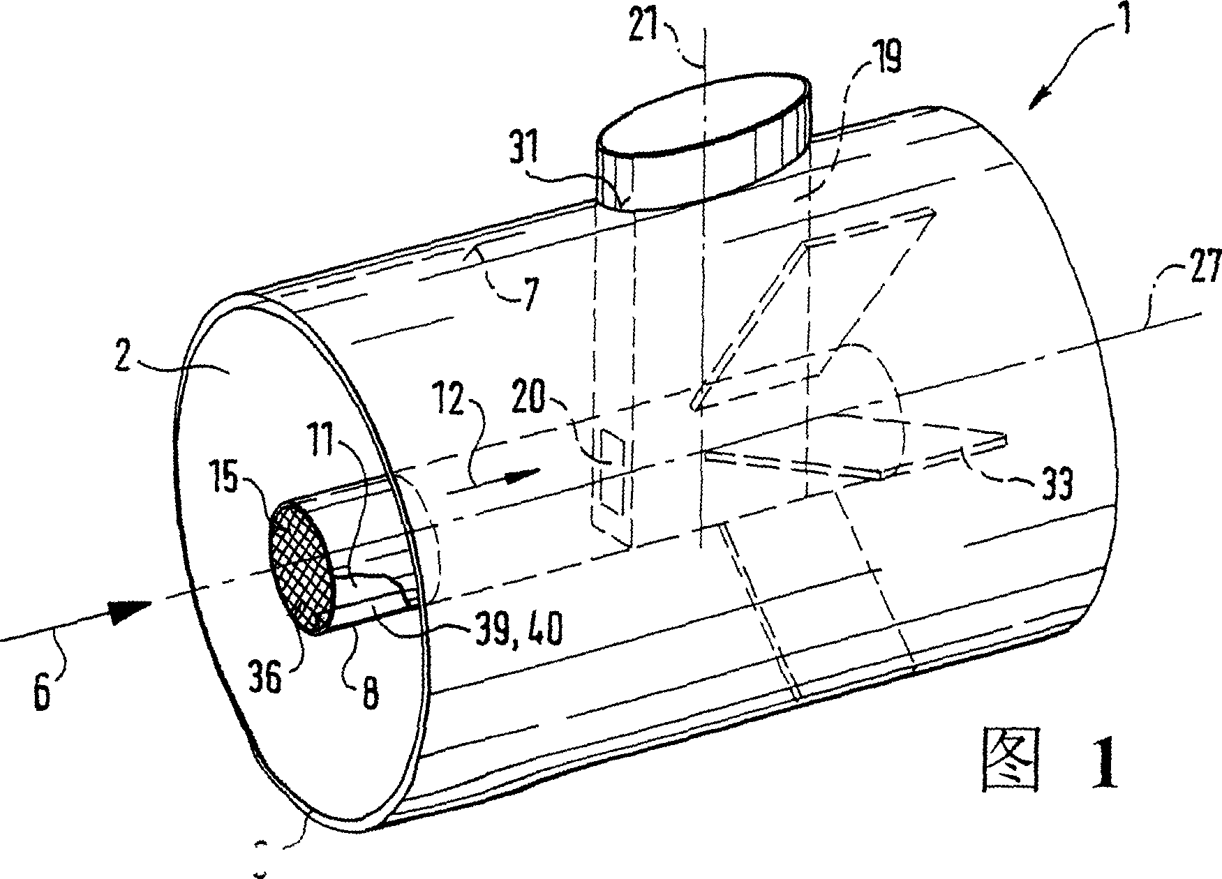
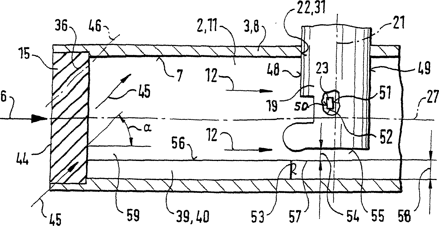
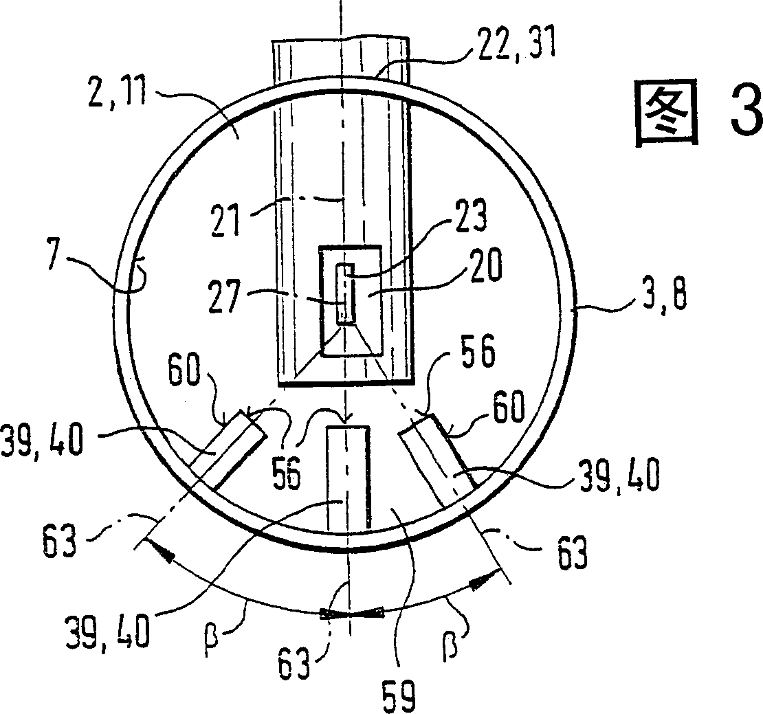
[0039] FIG. 1 shows a device 1 for measuring at least one parameter, in particular a parameter of the air mass flow, of a medium flowing in a line 2 , in particular of the intake air mass of an internal combustion engine. Parameters of a flowing medium include, for example, air mass flow, temperature, pressure or volume flow velocity for ascertaining the air mass, which are determined by suitable sensors. Other parameters can also be measured using the device 1 . The pipe 2 has a pipe wall 3 . In the line 2 the medium flows along the main flow direction 6 indicated by the arrow. The pipe 2 has an inner wall 7 . In the pipe 2 there is, for example, a pipe body 8 distributed radially at a certain distance from the pipe 2 and through which the medium flows. The tubular body 8 has a throughflow channel 11 and a protective grid 15 is arranged in its end region upstream in the direction of fluid flow. The protective grid 15 can be a wire braid, or a plate-shaped grid. It can al...


PUM


Abstract

The invention relates to a device (1) for measuring at least one parameter of a medium flowing in a pipe (2), especially the induced air mass of an internal combustion engine. Liquid particles contained in said pipe act upon a measuring element (23) and influence a characteristic behaviour of said measuring element (23), which is used to determine parameters of the flowing medium. The measuring element (23) is located downstream of a protective grill (15, 95) in a pipe or a hollow body (8) in order to reduce the action of the liquid on said measuring element (23). Said protective grill deviates the flow of the medium and diverts the liquid particles. Longitudinal ribs provided downstream of the protective grill (15, 95), or an extraction opening (72) or a turbulator (95) reduce uncontrolled shedding of vortices.

Description

technical field [0001] The invention relates to a device for measuring at least one parameter of a medium flowing in a pipeline. Background technique [0002] DE 197 35 891 A1 discloses a measuring body for measuring the intake air mass which can be arranged in a purge channel of the intake tract of an internal combustion engine. It has a fluid and measuring channel, the latter substantially inclined with respect to the longitudinal axis of a pipe, and divided into an S-shaped curved channel connected thereto. A measuring cell is arranged in the measuring channel. The measuring element can be a microstructured sensor element with a dielectric film, as described in DE 4338891 A1 and US Pat. No. 5,452,610. Contamination of the measuring cell can occur as a result of water entering the intake duct, for example as a result of rain wetting the road. The dissolved natural salts contained in this mist cause the characteristic curve to shift due to the formation of a salt crystal...

Claims


Application Information

Patent Timeline
Patent Type & Authority Patents(China)
IPC IPC(8): G01F1/00F02D35/00F15D1/02G01F1/684G01F15/12G01P5/00
CPCG01F15/12G01F1/6842G01F5/00G01F15/125G01F1/704
Inventor 托马斯·伦津克劳斯·雷曼迪特尔·汤克乌韦·康策尔曼瓦尔德马·京特霍斯特·库比茨
Owner ROBERT BOSCH GMBH
Learn More