Method for allocating radio channel for radio communication

A distribution method and wireless communication technology, which are applied in the directions of wireless communication, communication between multiple stations, electrical components, etc., can solve the problems of large total number, ineffective use of wireless lines, and inability of communication terminals to allocate wireless lines, and improve the effect of speed

Inactive Publication Date: 2004-08-11
MITSUBISHI ELECTRIC CORP
View PDF1 Cites 0 Cited by
  • Summary
  • Abstract
  • Description
  • Claims
  • Application Information

AI Technical Summary

Problems solved by technology

[0005] However, when there are more communication terminals using only small-capacity wireless lines than the total number of small-capacity wireless lines, there will be some communication terminals that cannot be allocated to wireless lines
On the other hand, if a large-capacity wireless line is allocated to communication terminals that cannot be allocated to the wireless line, there is a problem that the wireless line cannot be effectively used.

Method used


Image

  • Method for allocating radio channel for radio communication
  • Method for allocating radio channel for radio communication
  • Method for allocating radio channel for radio communication

Examples


Embodiment Construction

[0041] Hereinafter, in order to describe the present invention in more detail, the best mode for carrying out the present invention will be described with reference to the drawings.

[0042] Embodiment 1

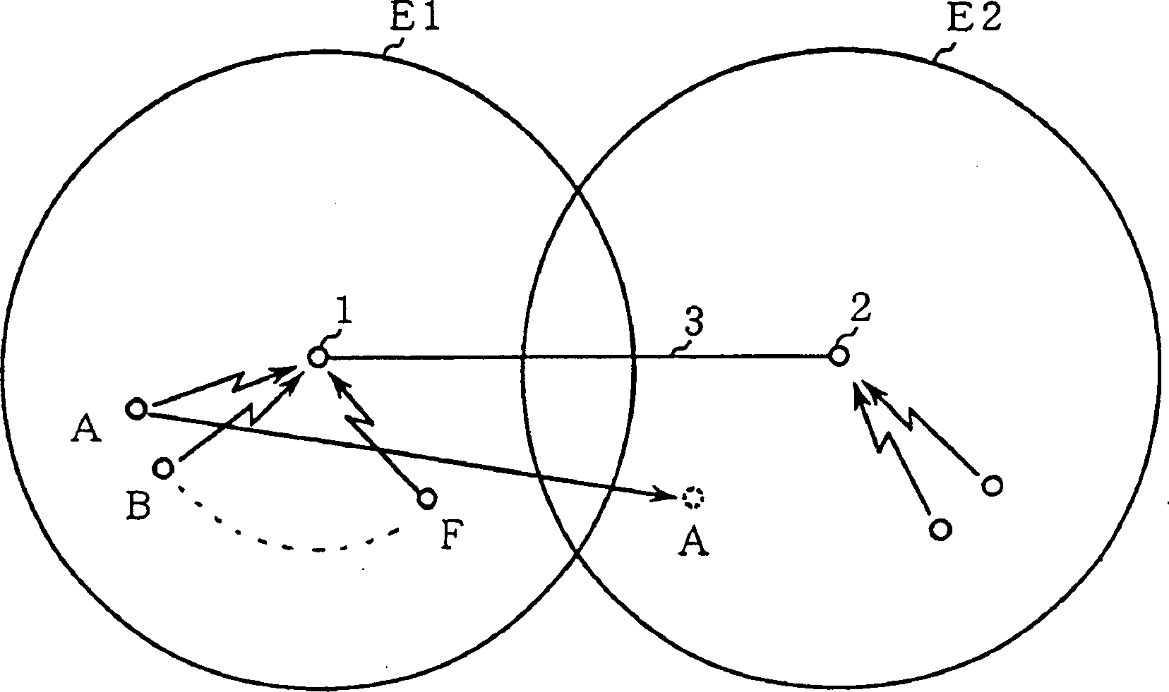
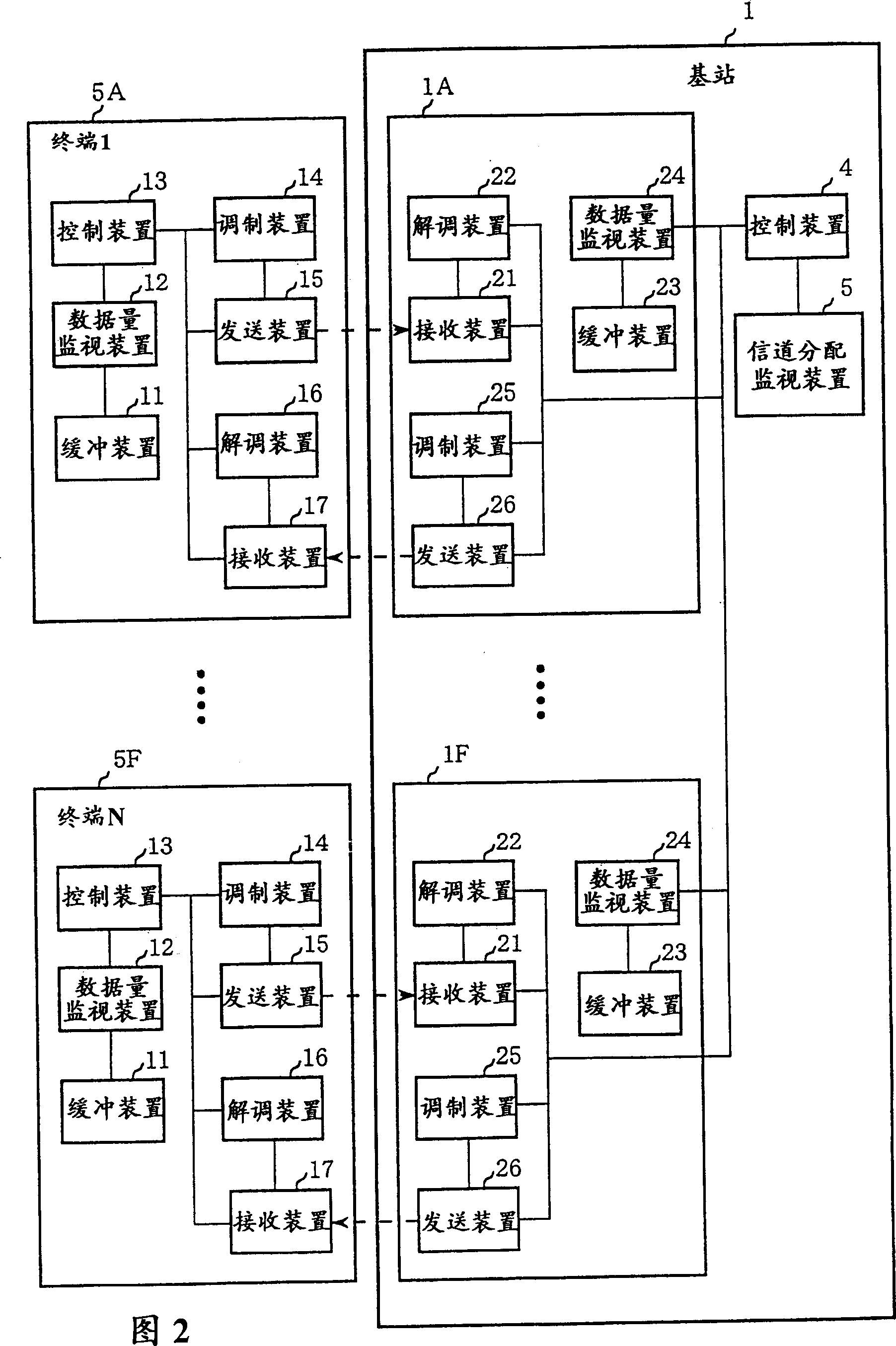
[0043] Fig. 2 is a block diagram showing a radio communication system according to Embodiment 1 of the present invention in which a plurality of radio terminals A(5A) to F(5)F communicate with one base station 1 by frequency division multiple access (FDMA).

[0044] The above-mentioned wireless terminals A (5A) to F (5F) each have a buffer device 11 for storing transmission data, for example, a data volume monitoring device 12 for detecting the amount of data stored in the buffer device 11 in the form of software according to a program, and for the wireless terminal The control device 13 for controlling, the modulation device 14 for modulating (changing the bandwidth) according to the judgment result of the control device 13 , the transmitting device 15 , the demodulating de...


PUM


Abstract

At the time of making radio communication between one base station and a plurality of radio terminals in the communication area of the base station, data communication is made at a higher speed and the wasteful use of the channel capacity is reduced by effectively using a limited channel capacity by changing the channel capacity, such as the number of channels, number of slots, frequency bandwidths, etc., in accordance with the rate of change of the quantity of communication data or quantity of communication data per unit time.

Description

technical field [0001] The present invention relates to a method of allocating radio lines during radio communication between a base station and a plurality of radio terminals such as portable radio telephones, cordless telephones, and portable telephones (PHS) located in the communication area of ​​the base station. Background technique [0002] figure 1 It is a diagram showing the configuration of a conventional general communication network system, and a base station 1 in a communication area E1 and a base station 2 in a communication area E2 are connected via, for example, a public telephone network 3 . Furthermore, the wireless terminals A to F in the communication area E1 communicate with the base station 1 by, for example, Frequency Division Multiple Access (FDMA) or Time Division Multiple Access (TDMA). [0003] In this case, since the communication data volume of the wireless terminals A to F is fixed when they are used as normal telephones, it is sufficient to all...

Claims


Application Information

Patent Timeline
Patent Type & Authority Patents(China)
IPC IPC(8): H04W72/04H04W72/08H04W72/10H04W74/04H04W88/08
CPCH04W74/04H04W72/08H04W72/0486H04W72/10H04W72/52H04W72/54H04W72/56
Inventor 丸山和彦
Owner MITSUBISHI ELECTRIC CORP
Why Eureka
Try Eureka