DC motor

A DC motor and commutator technology, applied in the field of brush DC motors, can solve problems such as poor space efficiency and workability, and achieve the effects of low manufacturing cost, noise removal, and good workability

Inactive Publication Date: 2004-06-02
RICOH KK
View PDF2 Cites 1 Cited by
  • Summary
  • Abstract
  • Description
  • Claims
  • Application Information

AI Technical Summary

Problems solved by technology

In this case, the noise generated by the motor can be eliminated in the motor itself, but since the commutator uses a general cylindrical structure, the space efficiency is poor, and the problem of workability in assembly still exists.

Method used


Image

  • DC motor
  • DC motor
  • DC motor

Examples


Embodiment Construction

[0100] The embodiments of the present invention will be described in detail below with reference to the drawings.

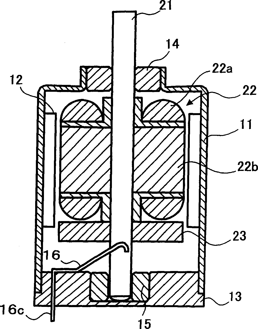
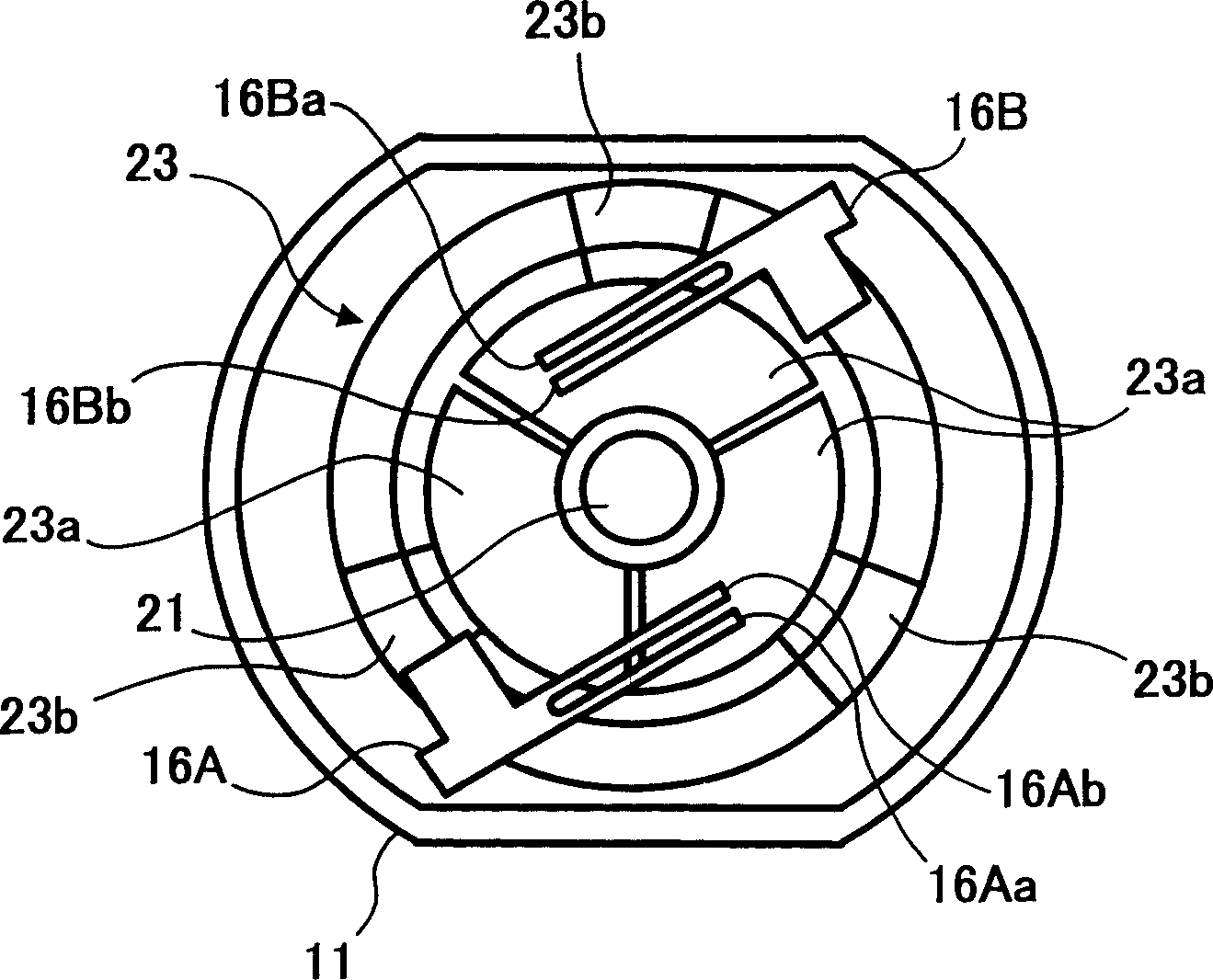
[0101] figure 1 with figure 2 Shows the DC motor related to the first embodiment of the present invention, figure 1 Is the longitudinal section view of the DC motor, figure 2 Is for illustration figure 1 A cross-sectional view of the structure of the sliding part of the DC motor commutator and electrode brushes.

[0102] figure 1 with figure 2 The DC motor shown is provided with a housing 11, a stator 12, a thrust bearing cover 13, an upper bearing 14, a lower bearing 15, an electrode brush 16, a rotating shaft 21, a rotor 22, and a printed circuit board 23. The housing 11, the stator 12, the thrust bearing cover 13, the upper bearing 14, the lower bearing 15, and the electrode brush 16 belong to the stator side structure and do not rotate. The rotating shaft 21, the rotor 22, and the printed circuit board 23 belong to the rotor side structure, are integrated...


PUM


Abstract

To achieve satisfactory workability in assembly, high mass- productivity, and miniaturization by reducing the overall dimension in the thrust direction. A rotating shaft 21 is rotatably supported to a case 11 by an upper bearing 14 and a lower bearing 15, and a rotating shaft 22 is formed so that a rotor coil 22a may be wound around a rotor core 22b. A printed circuit wiring board 23 is fixed to the rotating shaft so as to be perpendicularly intersected by the rotating shaft at the center part. The printed circuit wiring board 23 has contact electrode section. The contact electrode section 23a is connected to a rotating coil 22a through a conductive foil part. With a brush for electrodes and a brush for detecting rotation, a tip slides on and comes into contact with the contact electrode that is formed on the printed- wiring board.

Description

Technical field [0001] The present invention relates to a brush type DC motor, and more particularly to a DC motor such as a small motor used in precision machinery such as cameras. Background technique [0002] In a brush type DC motor, the rotor wound with the rotor coil is fixed on the rotating shaft, and the magnetic field is applied to the rotor by the stator through the magnetic poles opposite to the above-mentioned rotor magnetic poles. As the rotor rotates, the electrode brushes and rectification Sub, while switching, supply power to the above-mentioned rotor. The commutator is connected to the rotor coil and is composed of contact electrode parts integrated with the rotation shaft and divided into several in the rotation direction, and driving power is supplied from a driving DC power supply to the electrode brushes slidably contacting the contact electrode parts. That is, the DC power applied to the electrode brush is switched to the rotor coil by switching the contact ...

Claims


Application Information

Patent Timeline
Patent Type & Authority Patents(China)
IPC IPC(8): H01R39/06H01R39/24H02K13/00
CPCH02K13/006H01R39/24H01R39/06
Inventor 鹤川育也大野好美小山宪次
Owner RICOH KK
Why Eureka
Try Eureka