Apparatus for interfacing PDH network and ATM network

A quasi-synchronous digital and systematic technology, applied in the direction of transmission system, network interconnection, time division multiplexing system, etc., can solve the problem that the board can no longer be used

Inactive Publication Date: 2004-05-26
SAMSUNG ELECTRONICS CO LTD
View PDF0 Cites 1 Cited by
  • Summary
  • Abstract
  • Description
  • Claims
  • Application Information

AI Technical Summary

Problems solved by technology

[0003] Therefore, users must not be able to buy other boards but only buy board...

Method used


Image

  • Apparatus for interfacing PDH network and ATM network
  • Apparatus for interfacing PDH network and ATM network
  • Apparatus for interfacing PDH network and ATM network

Examples


Embodiment Construction

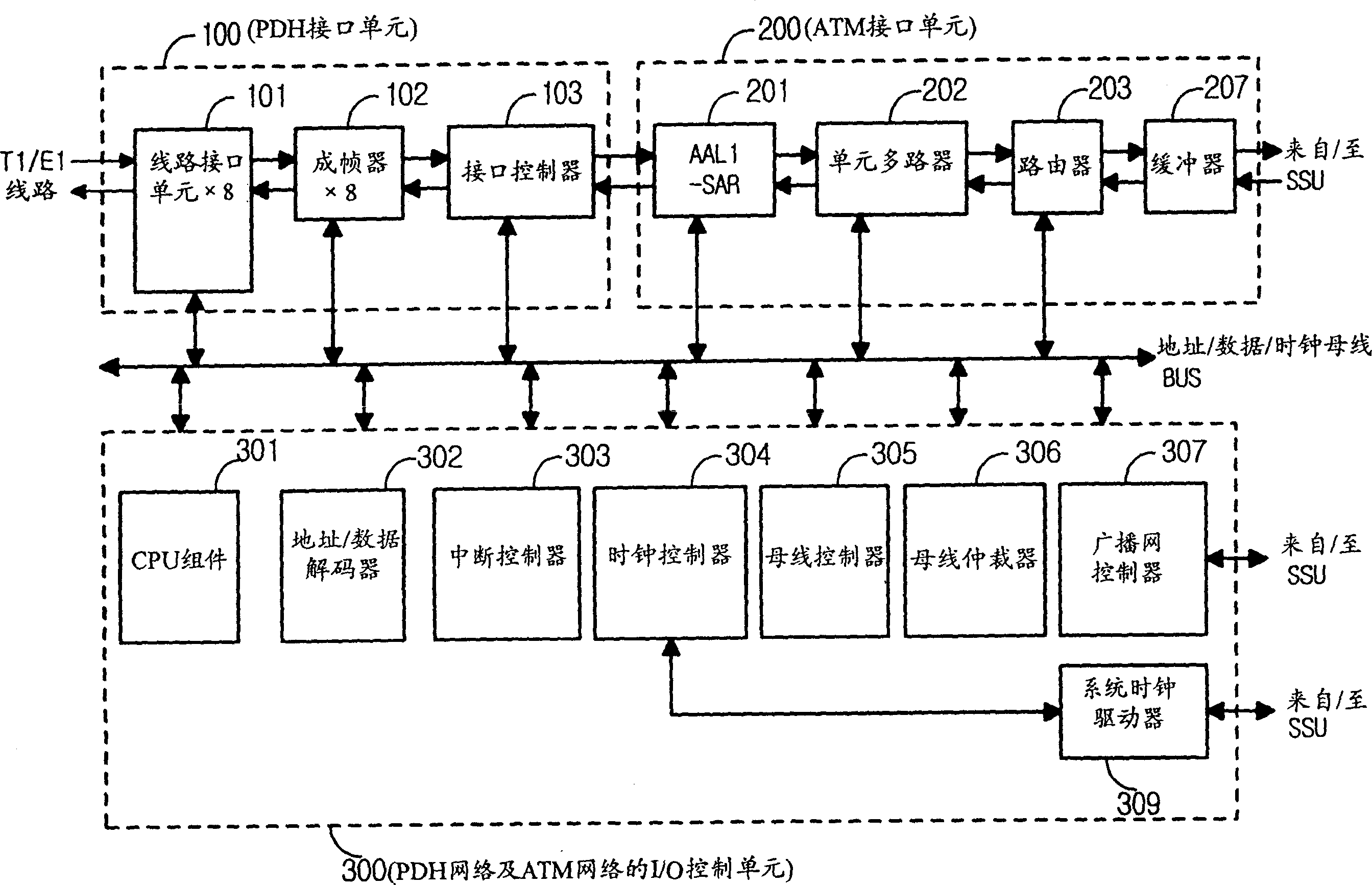
[0034] Usually, PDH network users who receive T1 or E1 transmission services through PABX (Private Automatic Branch Exchange) can be supported through the connection of ATM network. However, since the PDH network interface is different from the ATM network interface, an interface component is required which must perform interface matching.

[0035] The present invention relates to an interface component for a PDH network user receiving a T1 / E1 transport service as described above, to be supported by using an ATM network.

[0036] A preferred embodiment of the present invention will now be described with reference to the accompanying drawings.

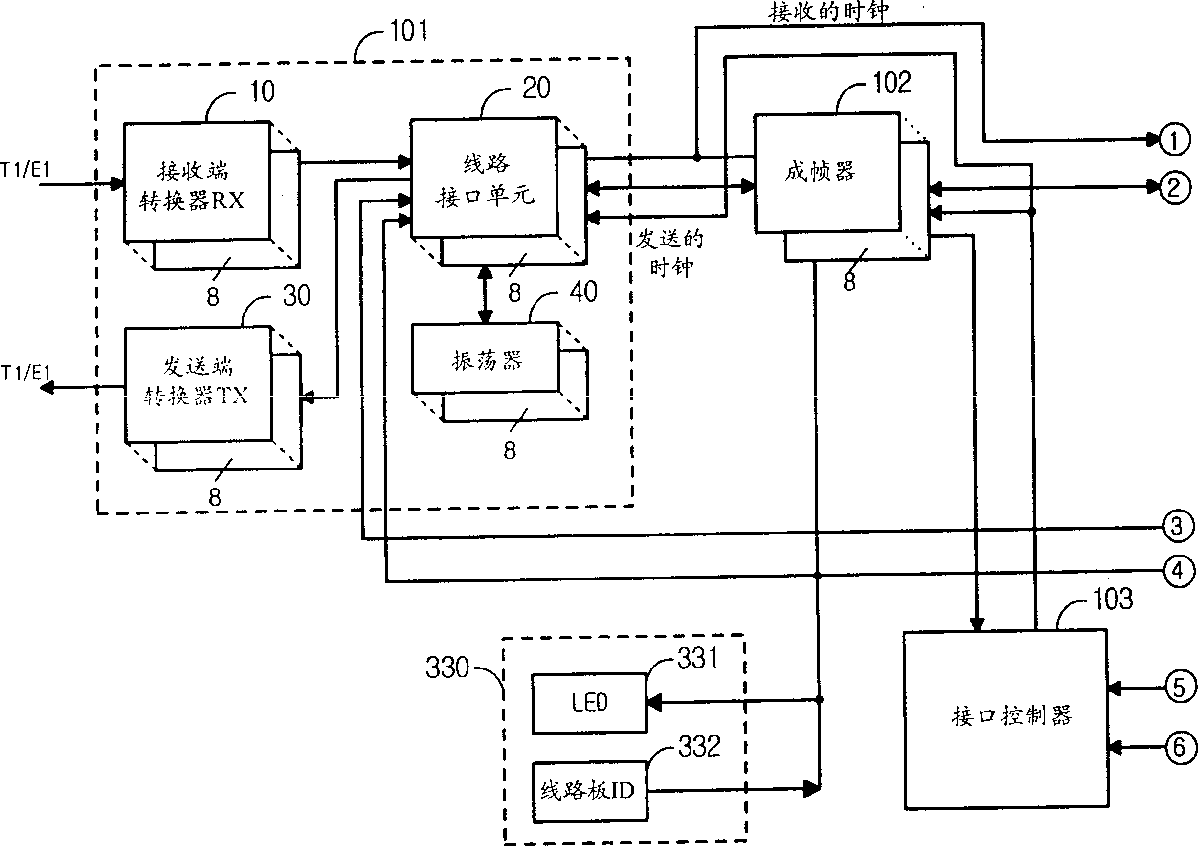
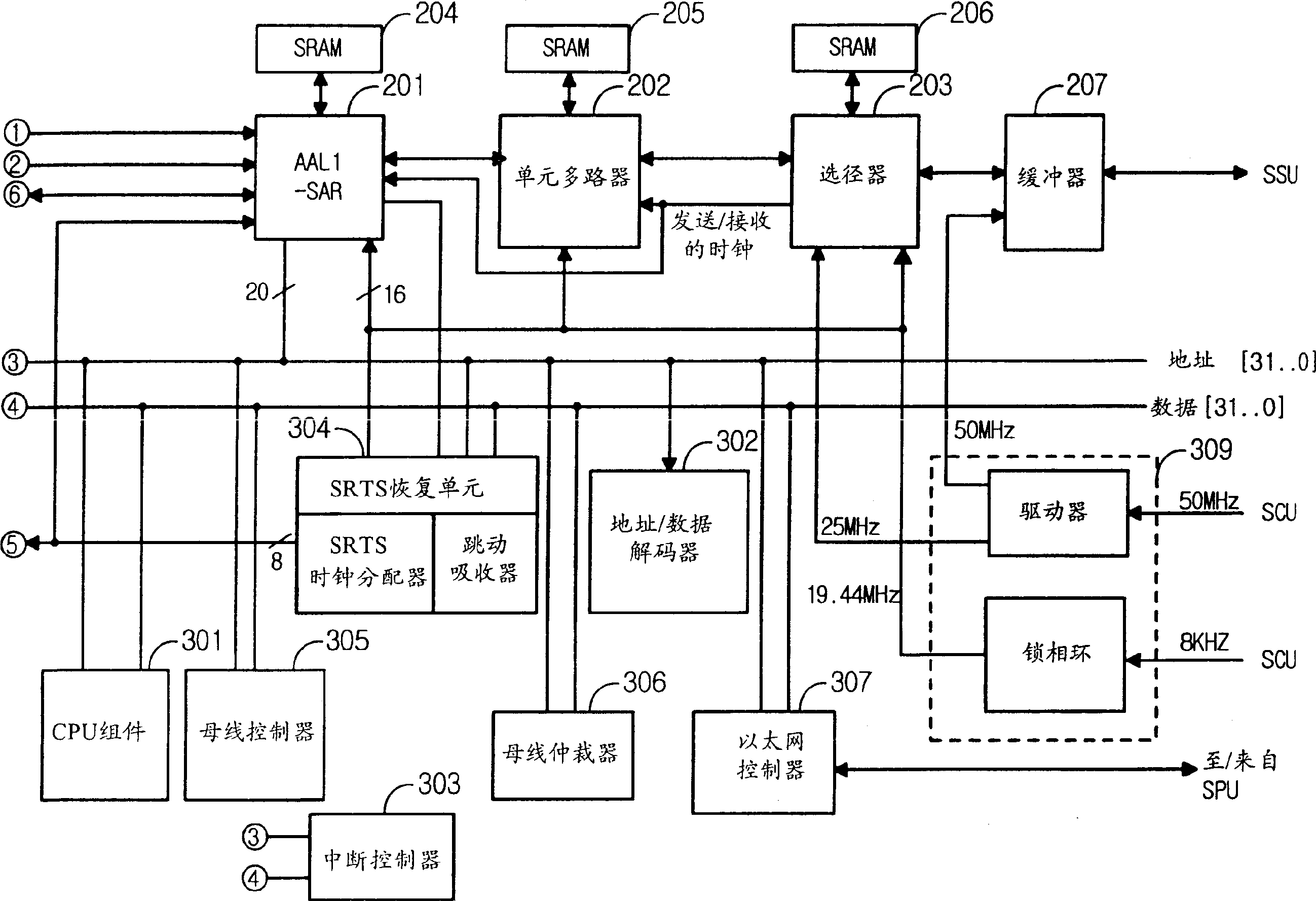
[0037] figure 1 shows a general diagram of the interface between the PDH network and the ATM network of the present invention, and Figure 2a or 2b represents according to an embodiment of the present invention figure 1 detailed circuit diagram. refer to figure 1 , Figure 2a or Figure 2b , to describe the transmission process...


PUM


Abstract

An interface apparatus of PDH network and ATM network which transmits data of positioning rate, e.g. pulse coding modulation voice signal of PDH network and real-time data via ATM network includes a line interface unit, a framer, an interface controller, a AAL1-SAR device, a cell multiplexer, a router, a buffer, a CPU assembly, an address/data decoder, an interrupt controller, a bus controller, an bus arbitrator, an Ethernet controller, a clock controller, and a system clock arbitrator.

Description

technical field [0001] The present invention relates to an interface device for a PDH (Pseudo-Synchronous Digital Hierarchy) network and an ATM (Asynchronous Transfer Mode) network, for transmitting CBR (Constant Bit Rate) data, such as voice data and real-time data in the PDH network, by using the ATM network . More specifically, the present invention relates to an interface device between a PDH network and an ATM network, which covers four services such as 1,544Mbps (megabit / second) (T1) rate, 2,048Mpbs (E1) using 1 interface device Rate, PDH original rate (T1 / E1) of T1 channelized (64kbps×24 time slots) data and E1 channelized (64kbps (kilobits / second)×30 timeslots or 64kbps×31 timeslots) data to connect to the ATM network. Background technique [0002] In the existing interface device, one PCB board is required to perform one interface function. In this case, for this interface device, it is an interface device that can make PDH network and ATM network work together, a...

Claims


Application Information

Patent Timeline
IPC IPC(8): H04L12/46H04J3/06H04J3/12H04J3/16H04L29/10
CPCH04J3/0602H04J3/1635H04J3/12H04L12/46H04L69/32
Inventor 元灿渊
Owner SAMSUNG ELECTRONICS CO LTD
Why Eureka
Try Eureka