
Flow direction control valve and heat pump system

A technology of flow direction control and heat pump system, applied in heat pumps, refrigerators, refrigeration components, etc., can solve problems such as high cost and complex system structure

Pending Publication Date: 2022-08-09
杭州熵竭科技有限公司
View PDF0 Cites 0 Cited by
  • Summary
  • Abstract
  • Description
  • Claims
  • Application Information

AI Technical Summary

Problems solved by technology

[0003] Most of the related technologies use two-way valves or three-way valves to switch and control the flow direction of refrigerants and other fluids, but it is difficult for the valve bodies 1 such as two-way valves or three-way valves to independently realize the switching control of fluids. Flow direction switching control also requires more auxiliary components, resulting in complex system structure and high cost

Method used


Image

  • Flow direction control valve and heat pump system
  • Flow direction control valve and heat pump system

Examples


Embodiment Construction

[0028] The embodiments of the present application will be described in further detail below with reference to the accompanying drawings and examples. The following examples are used to illustrate the application, but not to limit the scope of the application.

[0029] In the description of the embodiments of the present application, it should be noted that the terms "center", "portrait", "horizontal", "top", "bottom", "front", "rear", "left" and "right" , "vertical", "horizontal", "top", "bottom", "inside", "outside", etc. indicate the orientation or positional relationship based on the orientation or positional relationship shown in the accompanying drawings, only for the convenience of describing this The application examples and simplified descriptions are not intended to indicate or imply that the indicated devices or elements must have a specific orientation, be constructed and operated in a specific orientation, and therefore should not be construed as a limitation on th...


PUM


Abstract

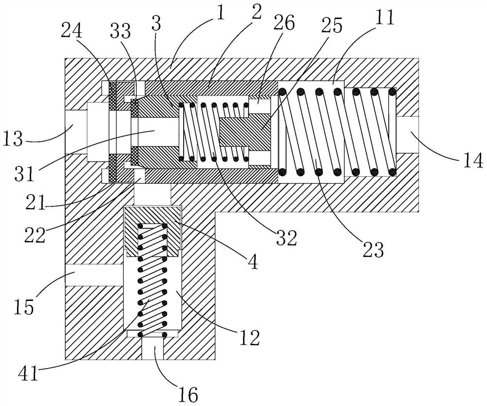
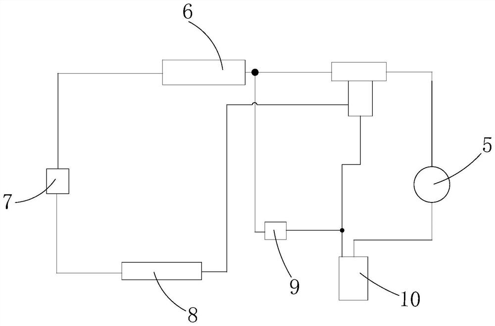
The invention relates to the technical field of flow direction control, and provides a flow direction control valve and a heat pump system. The flow direction control valve comprises a valve body, a first cavity and a second cavity which are communicated with each other are formed in the valve body, and the valve body is provided with a third connector, a fourth connector, a first connector and a second connector, the outer piston is in sliding connection with the first cavity, a gap communicated with the second cavity is formed in the outer piston, the other end of the outer piston is in sealed connection with the first cavity, and a pressure balance hole communicated with the second cavity is formed in one end of the outer piston; and the inner piston is in sealed sliding connection with the mounting cavity in the outer piston, and the inner piston can be switched between a compression state and an initial state. The side piston is connected with the second cavity in a sealed and sliding mode, and the side piston can be switched between a compression state and an initial state. According to the flow direction control valve, switching control over the flow direction of fluid such as refrigerants is achieved, the structure is simple, and cost is reduced.

Description

technical field [0001] The present application relates to the technical field of flow direction control, and in particular, to a flow direction control valve and a heat pump system. Background technique [0002] When a system with fluid flow such as a heat pump system is used, it is necessary to switch and control the flow direction of the refrigerant or the corresponding fluid. [0003] In the related art, two-way valves or three-way valves are mostly used to switch and control the flow direction of refrigerants and other fluids, and it is difficult for valve bodies 1 such as two-way valves or three-way valves to realize the switching control of the flow direction of the fluids alone. Flow direction switching control also requires more auxiliary components, resulting in complex system structure and high cost. SUMMARY OF THE INVENTION [0004] The present application aims to solve at least one of the technical problems existing in the related art. To this end, the presen...

Claims


Application Information

Patent Timeline
Patent Type & Authority Applications(China)
IPC IPC(8): F25B30/02F25B41/20F25B41/34
CPCF25B30/02F25B41/20F25B41/34
Inventor 南艳艳
Owner 杭州熵竭科技有限公司
Learn More