
Guide head mounting structure

A technology of installation structure and diversion head, which is applied in the direction of drill pipe, casing, measurement, etc., can solve the problems of drill collar and diversion head erosion, affect the service life, mud fluid turbulence, etc., and achieve uniform flow field and prolong Long service life, reduce the effect of fluid scouring

Pending Publication Date: 2022-08-09
CHINA OILFIELD SERVICES
View PDF0 Cites 0 Cited by
  • Summary
  • Abstract
  • Description
  • Claims
  • Application Information

AI Technical Summary

Problems solved by technology

[0002] Existing logging-while-drilling and directional logging tools include a drill collar and a diverter head installed in the through hole of the drill collar. Usually the diverter head is connected to the drill collar through screws along the axial direction. At this time, the through hole of the drill collar needs to be convex. There are installation steps and the diversion head needs to be provided with matching steps that match the installation steps for screw installation. However, in order to meet the strength requirements, the screws usually need to be set larger. Correspondingly, the size of the installation steps also needs to be set larger. When When the mud fluid flows through the installation step and the matching step, the mud fluid is prone to turbulent flow, which will cause erosion to the drill collar and the diversion head, and affect the service life

Method used


Image

  • Guide head mounting structure
  • Guide head mounting structure
  • Guide head mounting structure

Examples


specific Embodiment

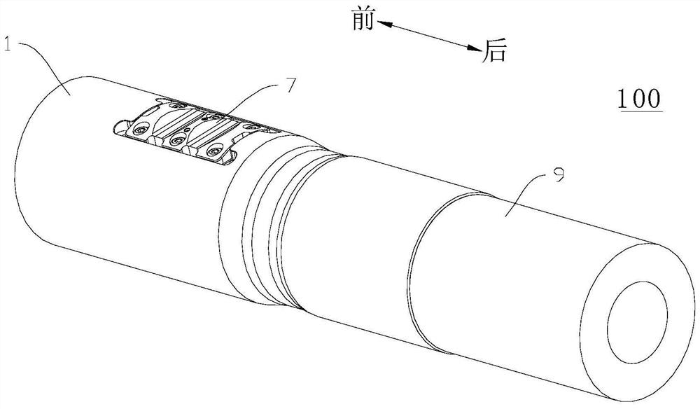
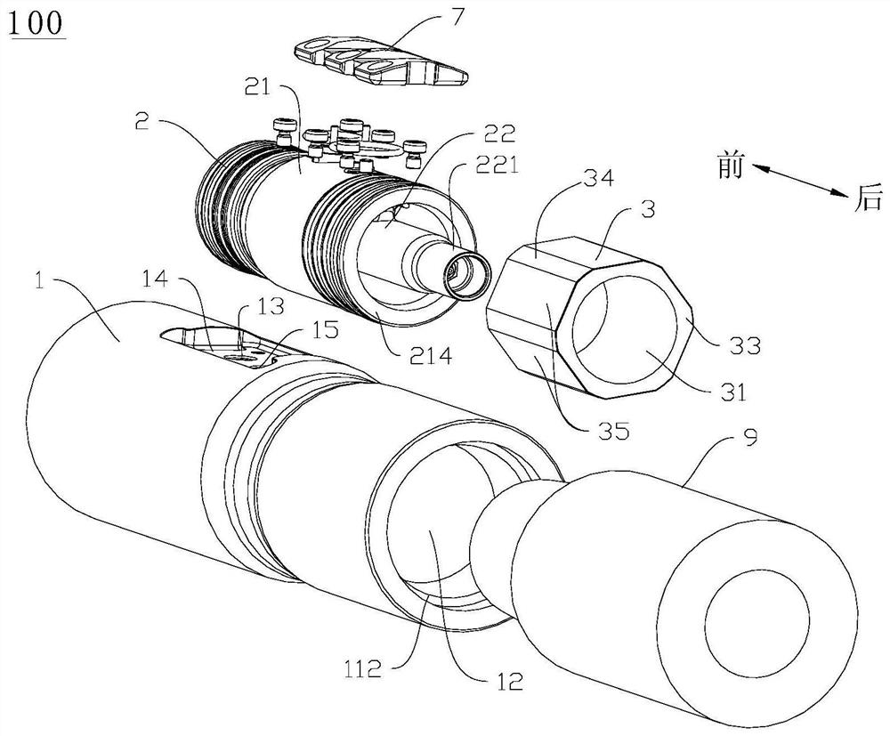
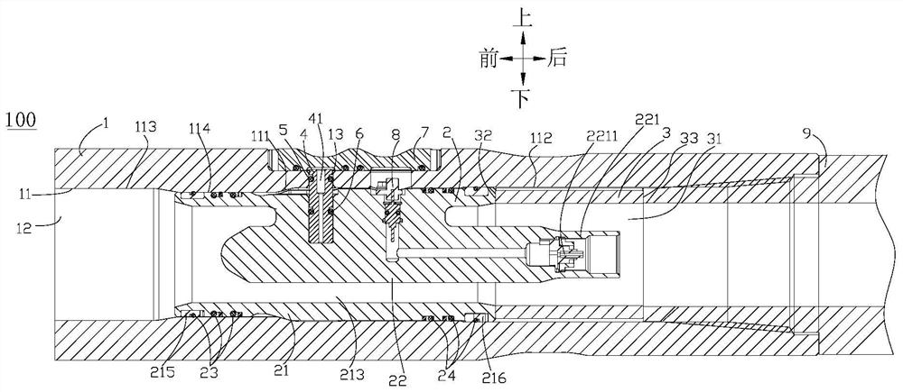
[0051] like Figure 1 to Figure 10 As shown, the guide head mounting structure 100 of the present embodiment is used for a 475-type LWD and directional logging tool, and the guide head mounting structure 100 is electrically connected to the docking piece. Of course, in other embodiments, the guide head mounting structure 100 can also be installed on other small-size LWD and directional logging instruments with an outer diameter less than 150 mm, or other guide head mounting structures 100 with the present invention can be used together Products used for mechanical support, sealing and electrical connection are not limited here.

[0052] like Figure 1 to Figure 4 As shown, the guide head installation structure 100 includes a drill collar 1, a guide head 2 and an elastic washer 3. The drill collar 1 is screwed with the docking housing 9, and the drill collar 1 is provided with a first direction extending in the first direction. A hole wall 11, the first hole wall 11 encloses ...


PUM


Abstract

The invention relates to the technical field of while-drilling and directional logging, in particular to a flow guide head mounting structure for electrical connection, which comprises a drill collar, a flow guide head and an elastic gasket, a first through hole for fluid to pass through is defined by a first hole wall of the drill collar, and a step surface is convexly arranged on the first hole wall; the flow guide head is installed in the first through hole and provided with a matching face matched with the step face in a stopping mode, the elastic gasket is installed in the first through hole and abuts against the flow guide head in the first direction, and the elastic gasket elastically deforms towards the step face in the first direction under the action of locking force so as to fasten the flow guide head to the drill collar. The flow guide head is positioned through the step surface, and then the flow guide head is limited and fixed between the step surface and the elastic gasket through the elastic gasket, so that the step surface can be set to be smaller, the flow field is uniform, the pressure drop is small, the machining requirements of the flow guide head, the drill collar and the elastic gasket are lower, the machining and assembling difficulty is reduced, the cost is reduced, and the mounting efficiency is improved.

Description

technical field [0001] The invention relates to the technical field of while drilling and directional logging, in particular to an installation structure of a diversion head. Background technique [0002] Existing LWD and directional logging tools include a drill collar and a guide head installed in the through hole of the drill collar. Usually, the guide head is axially connected to the drill collar by screws. At this time, the through hole of the drill collar needs to be convex. There is a mounting step and the guide head needs to be provided with a matching step that matches the mounting step for screw installation. However, in order to meet the strength requirements, the screw usually needs to be set larger. Correspondingly, the size of the installation step also needs to be set larger. When the mud fluid flows through the installation step and the matching step, the mud fluid is prone to turbulent flow, which will cause scouring of the drill collar and the guide head, a...

Claims


Application Information

Patent Timeline
Patent Type & Authority Applications(China)
IPC IPC(8): E21B17/16E21B17/04E21B47/00
CPCE21B17/16E21B17/04E21B47/00
Inventor 罗瑜林王清华药晓江丁元皓卢华涛贾立鹏
Owner CHINA OILFIELD SERVICES
Learn More