Guide knocking cap and prosthesis knocking device for joint replacement

A technology of joint replacement and knock cap, applied in the direction of joint implants, joint implants, etc., to achieve the effect of reducing radial component force

Pending Publication Date: 2022-08-09
LANCET ROBOTICS CO LTD
View PDF0 Cites 0 Cited by
  • Summary
  • Abstract
  • Description
  • Claims
  • Application Information

AI Technical Summary

Problems solved by technology

[0004] In order to solve the above problems, the object of the present invention is to provide a guiding knocking cap and a knocking device for joint replacement, which can reduce the impact on the mechanical arm during the contact and force transmission process between the knocking cap and the knocking rod. Excessive radial component forces cause the mechanical arm to trigger the force protection mechanism, causing the mechanical arm to lock up and fail to work normally, thereby avoiding the possibility of affecting the entire surgical process or even leading to surgical failure

Method used


Image

  • Guide knocking cap and prosthesis knocking device for joint replacement
  • Guide knocking cap and prosthesis knocking device for joint replacement
  • Guide knocking cap and prosthesis knocking device for joint replacement

Examples


Embodiment 1

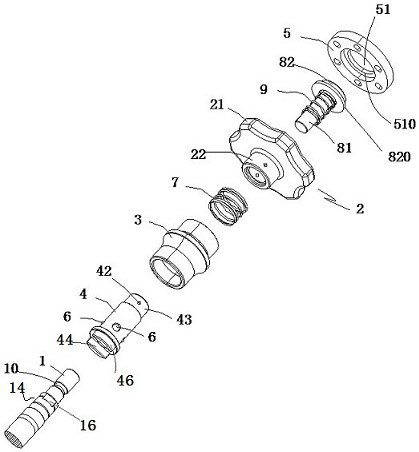
[0034] The striking device according to this embodiment further includes: a buffer sleeve, a flange end cover 5 of an impact rod 8 .

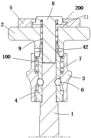
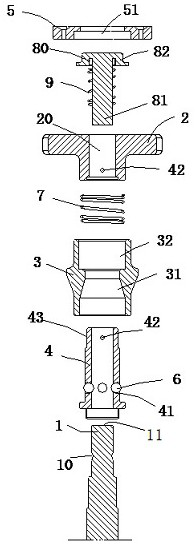
[0035] Here, the knocking portion 2 is configured as a T-shaped hollow sleeve structure with a mounting hole 20 formed therethrough in the axial direction, and includes an end portion 21 and a sleeve rod 22 . The upper end of the steel ball sleeve 4 penetrates into the stepped hole 32, and is connected with the lower end of the sleeve rod 22 extending into the stepped hole 32 through the tapered hole 42, and the outer axial direction of the steel ball sleeve 4 between the end of the sleeve rod 22 and the stepped hole 32 The sleeve is provided with a first spring 7 .

[0036] The impact rod 8 includes a rod portion 81 and a stepped head 82 . The lower end of the rod portion 81 passes through the mounting hole 20 and faces the end 11 of the knock rod 1 through the steel ball sleeve 4 to form an impact gap 100 . A buffer sleeve is axially sleeved...

Embodiment 2

[0053] The difference compared to Embodiment 1 mainly lies in the configurations of the buffer sleeve and the impact rod 8 .

[0054] like Image 6 As shown, in addition to the second spring 9, a shock absorbing pad 91 in the form of a rubber gasket or the like is provided as a buffer sleeve. The shock-absorbing pad 91 is fitted into the mounting hole 20, and the inner peripheral wall thereof is formed as a tapered wall surface 94 whose diameter increases toward the head 82 or the proximal side. The rod portion 81 has a conical section 84 matched with the conical wall surface, and in the initial installation state, the conical section 84 fits with the conical wall surface 94 .

[0055] In this way, during the transmission of the radial force Fr, in addition to the second spring 9, the damping pad 91 will also serve as a radial support, buffering effect.

[0056] Image 6 The lower end of the shock-absorbing pad 91 shown in the figure is supported on the stepped surface 23 ...

Embodiment 3

[0059] Figure 7 The difference between the shown buffer sleeve 93 and Embodiment 2 is that it is equivalent to the second spring 9 and the shock-absorbing pad 91 of Embodiment 2 being integrally connected in series, and part of the second spring 9 is upward from the shock-absorbing pad 91 . square out. This reduces assembly parts and simplifies assembly steps.


PUM


Abstract

The invention discloses a guiding knocking cap and a knocking device for joint replacement. Radial component force is effectively reduced in the force transmission process from the knocking cap to a knocking rod. The knocking cap comprises a knocking part, a pressure spring sleeve, a steel ball, a steel ball sleeve, a first spring, an impact rod, a buffering sleeve at least comprising a second spring and a flange end cover. The impact rod comprises a head part and a rod part. The second spring sleeves the periphery of the rod part and penetrates through the hollow hole part of the knocking part together with the rod part. The far end of the second spring abuts against the steel ball sleeve, and the near end of the second spring abuts against the head of the impact rod. The flange end cover is fixedly installed on the knocking part. In the initial state, the head part is far away from the knocking part towards the near side under the pre-tightening bias force of the second spring, and a flange part formed on the outer periphery of the head part is limited by a stop part of the flange end cover. After the head of the impact rod is knocked for the first time, the rod part knocks the knocking rod for the second time to achieve instantaneous impact force, and the knocking rod is driven to advance to complete installation of the acetabular cup. Meanwhile, the radial component force is buffered through elastic deformation of the second spring.

Description

technical field [0001] The invention relates to orthopaedic joint replacement technology, in particular to a guide knocking cap for joint replacement and a prosthetic knocking device with the knocking cap. Background technique [0002] For example, since knee and hip replacement surgery has evolved from traditional surgery to robotic intelligent navigation-assisted surgery, while improving the precision and dexterity of surgery, there are still technical problems that follow. For example, during the cup installation step of a surgical procedure, a force is applied to the tap rod along the guide of a robotic-assisted tool (grip) to hold the cup in place. [0003] However, when the doctor taps, the direction of the tapping force cannot be guaranteed to be consistent with the axial direction of the tapping rod. When a part of the radial force is transmitted to the tapping rod, the tapping rod, the gripper and other components are indirectly connected to the mechanical The arm ...

Claims


Application Information

Patent Timeline
Patent Type & Authority Applications(China)
IPC IPC(8): A61F2/46
CPCA61F2/46A61F2002/4681
Inventor 黄志俊刘金勇钱坤安永邵勇
Owner LANCET ROBOTICS CO LTD
Why Eureka
Try Eureka