
Stable structure of surrounding type sliding seat and square ram and mounting method of stable structure

A technology of stable structure and square ram, which is applied in the direction of large fixed members, metal processing equipment, metal processing machinery parts, etc., can solve the problems of affecting processing accuracy, damage of transmission structure, forward tilting of center of gravity, etc., and achieve the effect of improving processing accuracy

Active Publication Date: 2022-08-05
江苏贵钰航空工业有限公司
View PDF5 Cites 1 Cited by
  • Summary
  • Abstract
  • Description
  • Claims
  • Application Information

AI Technical Summary

Problems solved by technology

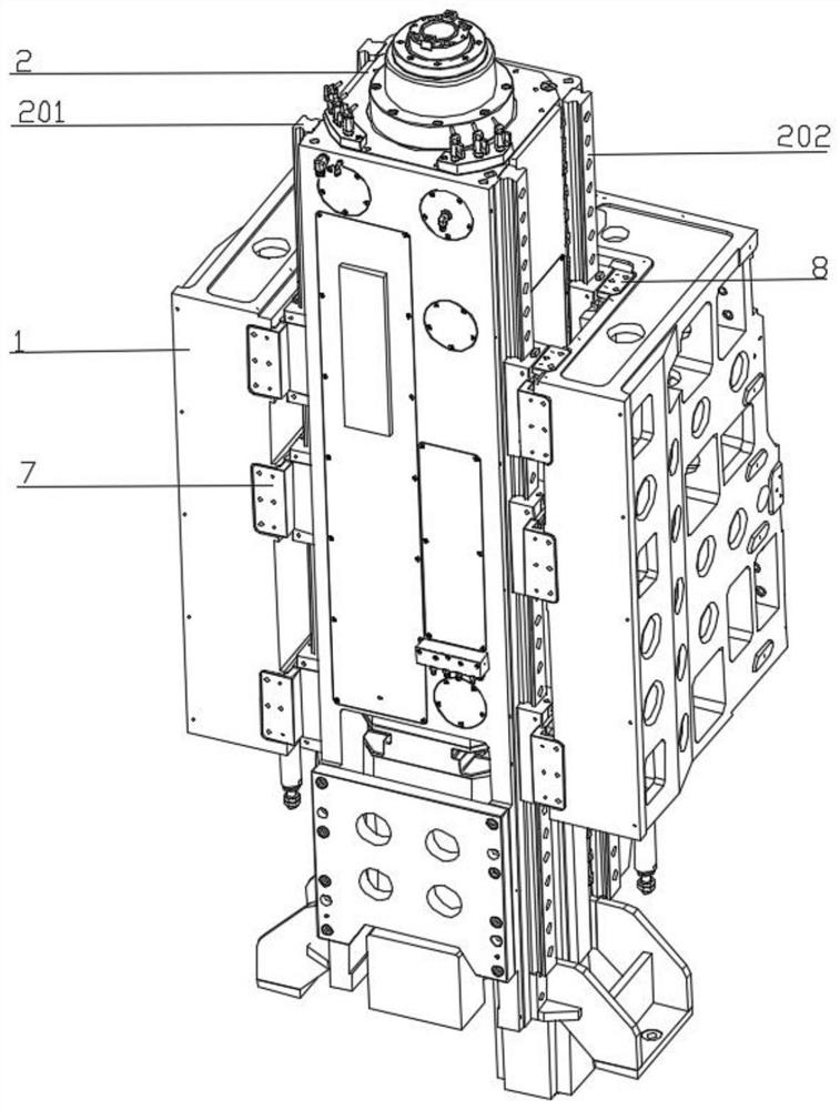
[0002] In the prior art, the core components of the vertical machine tool are the square ram and the slide seat on which the square ram is installed. The transmission between the slide seat and the square ram is carried out through the slide block and the guide rail, and the slide block is usually fixed on the On the sliding seat, this installation structure cannot achieve a complete fit between the sliding block and the sliding seat. During the transmission process, the square ram is easy to shake from side to side, which affects the machining accuracy. At the same time, the square ram structure of the machine tool has a front center of gravity. The defect of tilting, long-term operation will cause the deformation of the slider, which will affect the machining accuracy in the slightest, and cause damage to the transmission structure in severe cases, affecting the operation of the entire machine tool

Method used


Image

  • Stable structure of surrounding type sliding seat and square ram and mounting method of stable structure
  • Stable structure of surrounding type sliding seat and square ram and mounting method of stable structure
  • Stable structure of surrounding type sliding seat and square ram and mounting method of stable structure

Examples


Embodiment Construction

[0025] The present invention will be further clarified below in conjunction with the specific embodiments. It should be understood that these embodiments are only used to illustrate the present invention and not to limit the scope of the present invention. The modifications all fall within the scope defined by the appended claims of this application.

[0026] In the present invention, unless otherwise expressly specified and limited, terms such as "installation", "arrangement", "connection" and "fixed connection" should be understood in a broad sense, for example, it may be a fixed connection or a detachable connection Connected, or integrated; it can be a mechanical connection or an electrical connection; it can be directly connected or indirectly connected through an intermediate medium, it can be the internal communication between two elements or the interaction relationship between the two elements, unless otherwise Clearly defined, those of ordinary skill in the art can u...


PUM


Abstract

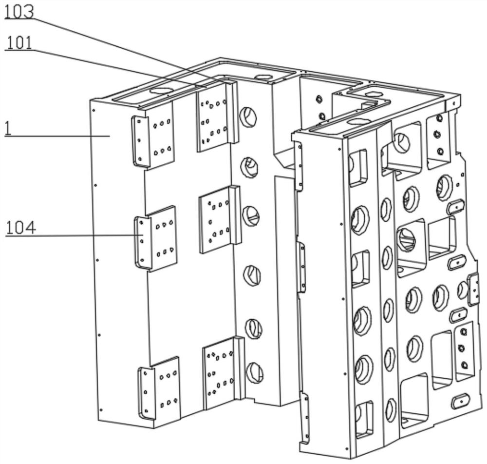
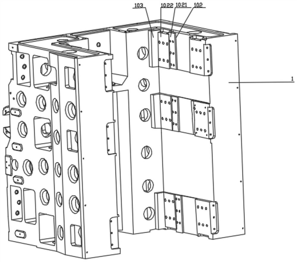
The invention provides a surrounding type sliding seat and square ram stabilizing structure and a mounting method thereof.The structure comprises a sliding seat and a square ram, the sliding seat is concave, guide rails are arranged on the two sides of the square ram, each guide rail comprises an inner side guide rail and an outer side guide rail, sliding blocks are arranged on the guide rails, and the two concave side faces of the sliding seat are a first mounting face and a second mounting face correspondingly; the plane installation seat of the first installation face is fixedly connected with the sliding blocks, wedge-shaped base plates are connected between the wedge installation seats of the second installation face and the sliding blocks in an inserted mode, the wedge installation seats, the wedge-shaped base plates and the sliding blocks are fixedly connected through bolts, bearing devices are arranged on the front end faces of the sliding blocks arranged on the inner side guide rails, and pressing plates are arranged on the front end faces of the sliding blocks arranged on the outer side guide rails. By the adoption of the structure, the square ram can be prevented from shaking forwards, backwards, leftwards and rightwards when running on the sliding base along the Z axis, and the machining precision of a machine tool is improved.

Description

technical field [0001] The invention relates to the technical field of large mechanical equipment, in particular to a stable structure of an encircling sliding seat and a square ram and an installation method thereof. Background technique [0002] In the prior art, the core components of a vertical machine tool are the square ram and the sliding seat on which the square ram is installed. The sliding block and the square ram are driven by the sliding block and the guide rail, and the sliding block is usually fixed by the tension bolt. On the sliding seat, this installation structure cannot completely fit the sliding block and the sliding seat. During the transmission process, the square ram is easy to shake left and right, which affects the machining accuracy. At the same time, the square ram structure of the machine tool has a front center of gravity. The defect of tilting and long-term operation will lead to the deformation of the slider, which will affect the machining acc...

Claims


Application Information

Patent Timeline
IPC IPC(8): B23Q1/01B23Q1/26
CPCB23Q1/015B23Q1/017B23Q1/267Y02E10/50
Inventor 王海龙伍志健
Owner 江苏贵钰航空工业有限公司
Learn More