
Connector and electronic equipment

A technology of connectors and grounding terminals, which is applied in the field of connectors and electronic equipment, and can solve problems such as high frequency resonance and poor high-speed transmission effect

Inactive Publication Date: 2022-08-02
HESHAN DEREN ELECTRONIC TECH CO LTD
View PDF0 Cites 0 Cited by
  • Summary
  • Abstract
  • Description
  • Claims
  • Application Information

AI Technical Summary

Problems solved by technology

[0003] However, in the process of realizing the embodiments of the present invention, the inventors found that: in order to realize the high-speed transmission and low-delay requirements of the connector, there are currently high-speed connectors, and the high-speed connector includes an insulating body, a first terminal and a second terminal , the first terminal includes a differential signal terminal and a ground terminal, the differential signal terminal and the ground terminal are arranged alternately, each ground terminal is isolated, the high-frequency resonance is high, and the high-speed transmission effect is poor

Method used


Image

  • Connector and electronic equipment
  • Connector and electronic equipment
  • Connector and electronic equipment

Examples


Embodiment 1

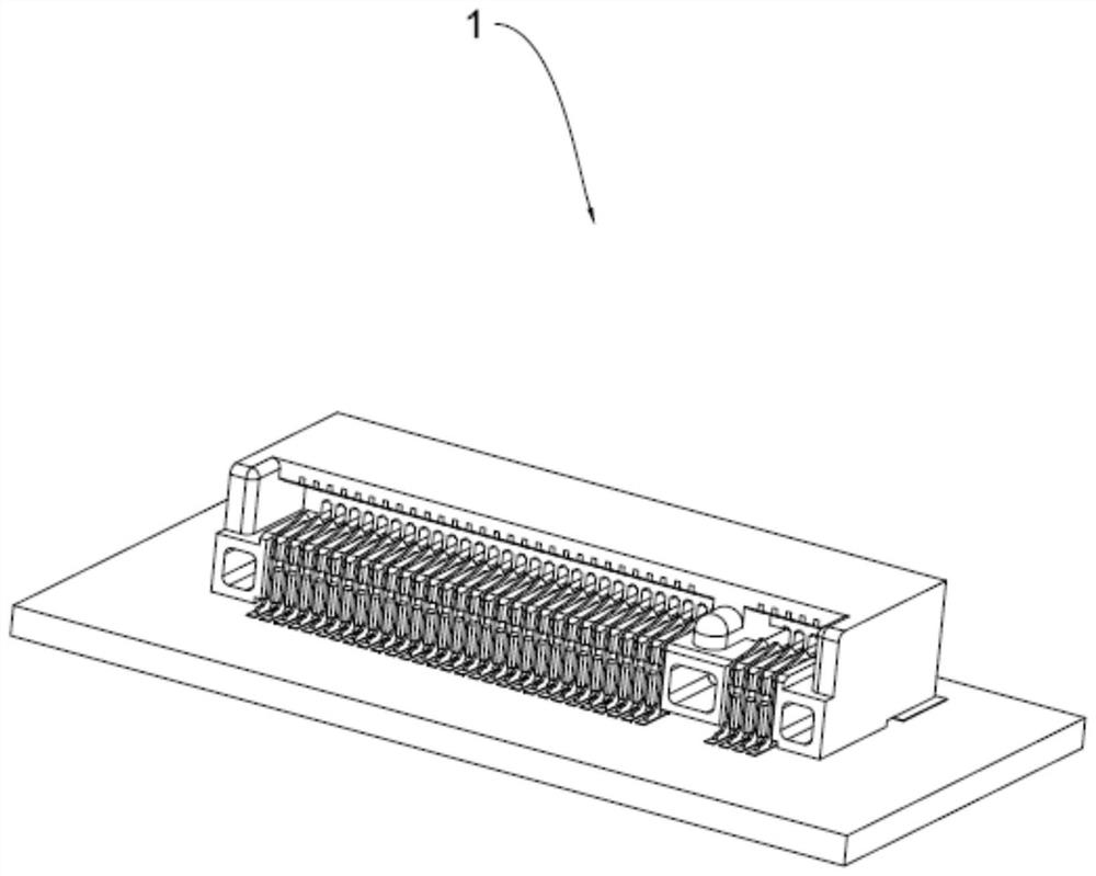
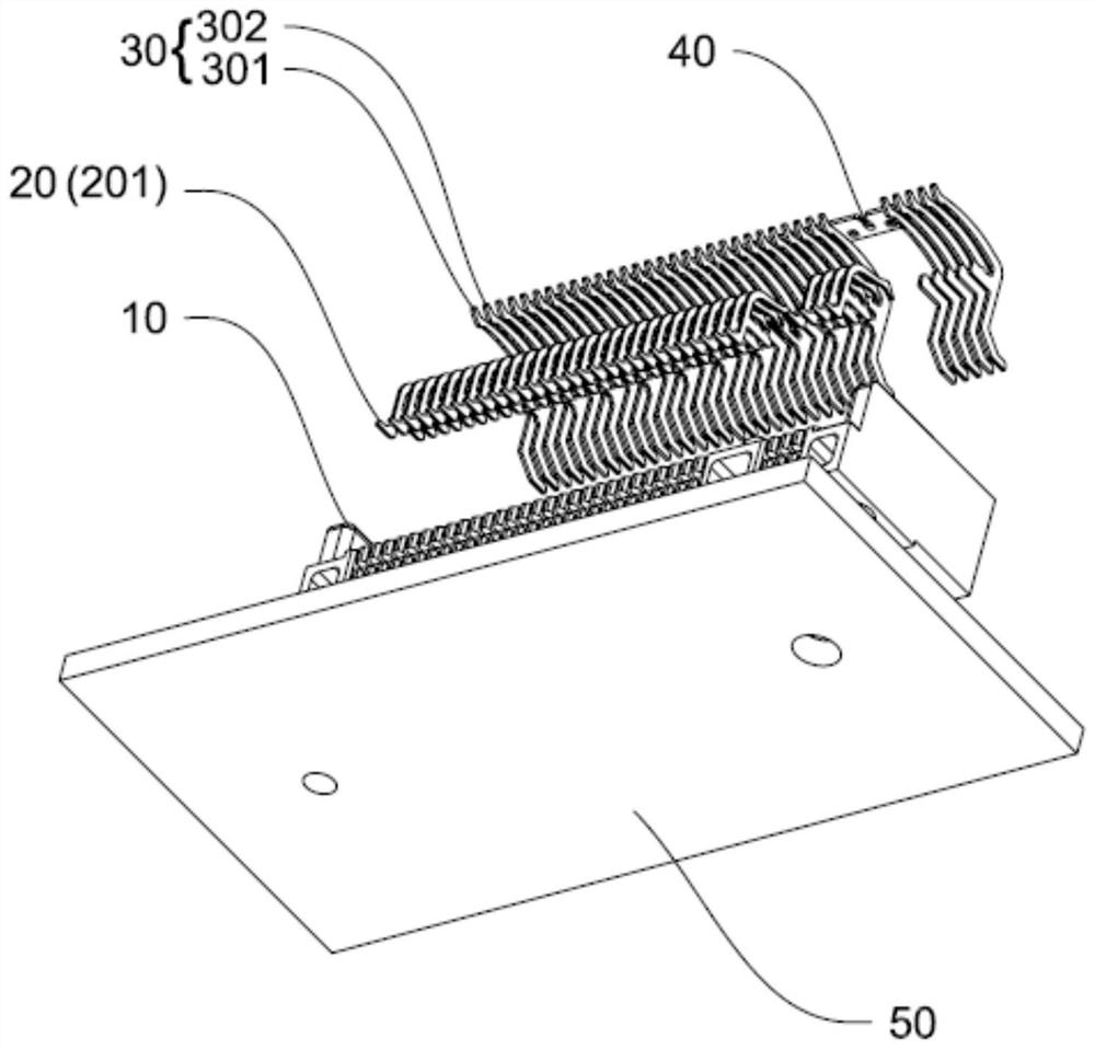
[0034] see figure 1 and figure 2 , the connector 1 includes an insulating body 10, a second terminal row 20, a first terminal row 30, a metal connecting piece 40 and a circuit board 50, the second terminal row 20 is arranged on the insulating body 10, and the second terminal row 20 partially extends The outside of the insulating body 10 is connected to the circuit board 50 , and the second terminal row 20 is used for conducting electricity. The first terminal block 30 is arranged on the insulating body 10, and part of the first terminal block 30 extends out of the insulating body 10 to be connected to the circuit board 50. The first terminal block 30 is used for grounding and transmitting high-speed signals. One end of the first terminal block 30 is connected to the circuit board 50. One end of the second terminal row 20 is disposed opposite to each other. The metal connecting piece 40 is arranged on the insulating body 10 , and some of the terminals in the first terminal r...

Embodiment 2

[0043] The difference between the second embodiment and the first embodiment is that the structures of the insulating body 10' and the ground terminal 301' are different. Specifically,

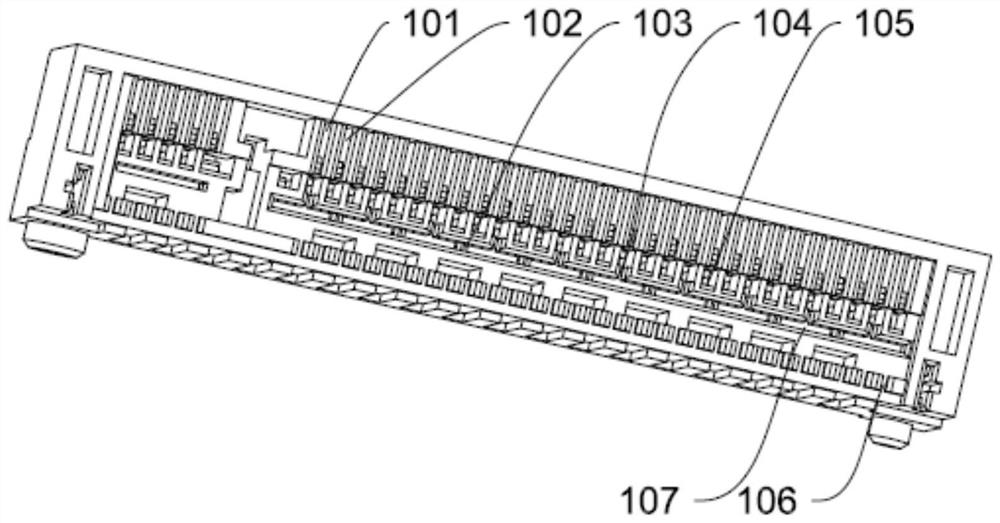
[0044] see Figure 11 and Figure 12 , the insulating body 10' is not provided with the first mounting groove 107 and the first fixing column 103 in the first embodiment, but the insulating body 10' is provided with several second fixing columns 115' and second mounting grooves 116'. The insulating body 10' is provided with a first receiving cavity 108', a plurality of first through holes 101', a plurality of second through holes 102', a plurality of first fixing grooves 104', a plurality of second fixing grooves 105', and a plurality of third fixing grooves 106', a plurality of fourth fixing grooves 109', a plurality of fifth fixing grooves 112', a plurality of sixth fixing grooves 113' and a plurality of seventh fixing grooves 114'. A through hole 101' and a second through hole 102' are di...


PUM


Abstract

The embodiment of the invention relates to the technical field of connectors, and particularly discloses a connector and electronic equipment, the connector comprises an insulating body, a first terminal strip, a metal connecting sheet and a second terminal strip, one end of the insulating body is provided with a first accommodating cavity, and the first terminal strip is arranged on the insulating body; the first terminal row at least comprises a plurality of grounding terminals and a plurality of pairs of differential signal terminals, one ends of the grounding terminals and one ends of the differential signal terminals extend into the first accommodating cavity, the grounding terminals are arranged between one pair of differential signal terminals and the other pair of differential signal terminals, and the grounding terminals extend to form abutting parts; the metal connecting piece is arranged on the insulating body and is in surface contact with the abutting part, the second terminal row comprises conductive terminals, one end of each conductive terminal extends to the first containing cavity, and one end of each conductive terminal is arranged opposite to one end of the corresponding grounding terminal and one end of the corresponding differential signal terminal. By means of the mode, high-frequency resonance of the connector is reduced, and high-speed signal transmission is facilitated.

Description

technical field [0001] Embodiments of the present invention relate to the technical field of connectors, and in particular, to a connector and an electronic device. Background technique [0002] With the development of science and technology, the amount of information transmission is increasing, and the requirements for high-speed and low-latency transmission are getting higher and higher. Connectors are commonly used electrical components for signal transmission. The need for low latency. [0003] However, in the process of implementing the embodiments of the present invention, the inventor found that: in order to meet the requirements of high-speed transmission and low-latency of the connector, a high-speed connector now appears, and the high-speed connector includes an insulating body, a first terminal and a second terminal. , the first terminal includes a differential signal terminal and a ground terminal, the differential signal terminal and the ground terminal are alt...

Claims


Application Information

Patent Timeline
IPC IPC(8): H01R13/02H01R13/40H01R13/646H01R13/652H01R13/502H01R12/71
CPCH01R13/02H01R13/40H01R13/646H01R13/652H01R13/502H01R12/716
Inventor 林宗彪
Owner HESHAN DEREN ELECTRONIC TECH CO LTD
Learn More