Method for realizing flight control of A-wing aircraft

A flight control and A-wing aircraft technology, applied in the aviation field, can solve the problems of conflicting vertical take-off and landing modes, low flight efficiency, poor safety, etc., to improve the vertical take-off and landing capability, compress the vertical take-off and landing time, and reduce the side area. Effect

Pending Publication Date: 2022-08-02
KUNMING QIAOYI SCI & TECH CO LTD
View PDF0 Cites 0 Cited by
  • Summary
  • Abstract
  • Description
  • Claims
  • Application Information

AI Technical Summary

Problems solved by technology

[0005] The technical problem to be solved by the present invention is to propose a method to realize the flight of the armored wing aircraft in view of the existing problems such as the low flight efficiency of the vertical take-off and landing aircraft, the small load capacity, the complicated control, the poor safety, the conflict between the horizontal flight mode and the vertical take-off and landing mode, etc. In the control method, there are driving devices on the upper and lower parts of the wings, and at the same time, the large-area wings and the driving devices are divided into several partitions to be controlled respectively. The pressure on the wing surface adjusts the flight attitude of the large-area shell-shaped wide-chord wing by changing the pressure on the top and bottom of the wing in each partition, and realizes the flight control of the armored wing aircraft

Method used


Image

  • Method for realizing flight control of A-wing aircraft
  • Method for realizing flight control of A-wing aircraft
  • Method for realizing flight control of A-wing aircraft

Examples


Embodiment 1

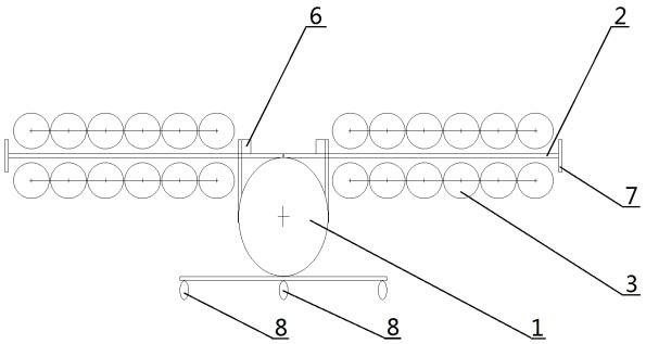
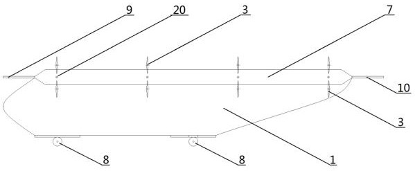
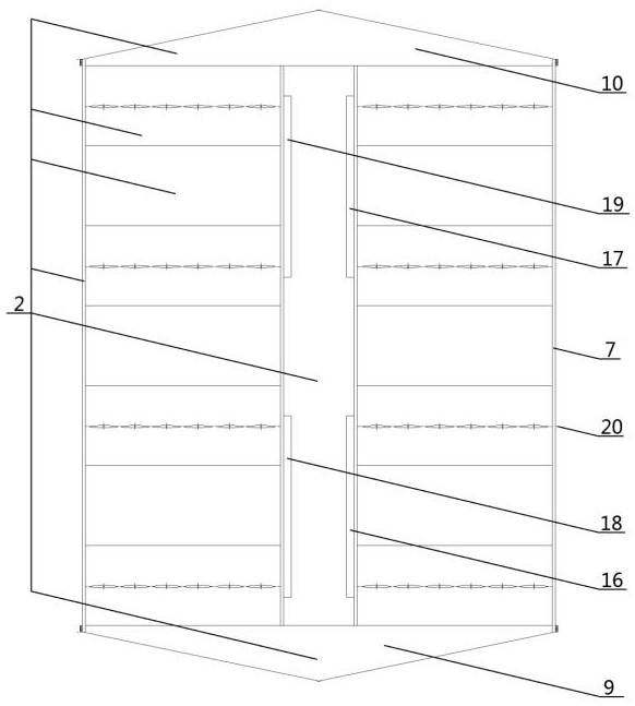
[0053] Example 1: as Figure 1-20 As shown in the figure, the method for realizing the flight control of the wing aircraft, the wing aircraft has a large-area shell-shaped wide-chord wing, the upper and lower parts of the shell-shaped wing are respectively fixed with drive devices, and the drive devices are arranged in two rows along the chord direction of the wing. , Densely distributed along the span of the wing, the thickness of the driving device to generate a layered driving airflow on the surface of the wing is less than 0.2 times the chord length of the large-area shell-shaped wide-chord wing; the large-area shell-shaped wide-chord wing is designed as a combined type , it is divided into 4 sections of tilting wing and 5 sections of fixed wing. The many driving devices are divided into four sections, the left front section and the right front section, with the aerodynamic center of the large-area shell-shaped wide-chord wing as the origin. The partitions include 2 sectio...

Embodiment 2

[0063] Example 2: as Figure 1-22 As shown in the figure, the method for realizing the flight control of an A-wing aircraft, the single-seat sports A-wing aircraft has a large-area shell-shaped wide-chord wing, and the upper and lower parts of the shell-shaped wing are respectively fixed and installed with driving devices; The aerodynamic center of the large-area shell-shaped wide-chord wing is used as the origin to divide the wing and the driving device into four sections. Wings, front left and right front divisions both include 1 section of tilting wing and 2 sections of fixed wing, and left rear section and right rear section both include 1 section of tilting wing and 1 section of fixed wing. The aspect ratio of the single-seat sports A-wing aircraft is λ=l / b=2, and the chord length of the tilting wing is 1.5 meters. A row of propellers with a diameter of 0.7 meters is arranged on the upper and lower parts of each tilting wing, and the number of propellers in each row is 6...

Embodiment 3

[0064] Example 3: as Figure 1-20 As shown in , 23-24, this method for realizing the flight control of the wing aircraft, the 3-seat family wing aircraft has a large-area shell-shaped wide-chord wing, and the upper and lower parts of the shell-shaped wing are respectively fixed with driving devices; The driving device takes the aerodynamic center of the large-area shell-shaped wide-chord wing as the origin to divide the wing and the driving device into four sections, and the large-area shell-shaped wide-chord wing is designed as a combined type, which is divided into 6 sections of tilting wings laterally. and 3-section fixed wing, the left front section and right front section both include 3-section tilting wing and 2-section fixed wing, and the left rear section and right rear section both include 3-section tilting wing and 1-section fixed wing. The aspect ratio of the 3-seat family A-wing aircraft is λ=l / b=0.7, and the chord length of the tilting wing is 1.5 meters. A row o...


PUM


Abstract

The invention discloses a method for realizing flight control of an A-wing aircraft, and belongs to the technical field of aviation. The A-wing aircraft is provided with a large-area shell-shaped wide-chord wing, a plurality of rows of driving devices are arranged above and below the shell-shaped wing, and layered driving airflow is generated on the surface of the wing; the wing and the driving devices are divided into a plurality of subareas by taking the pneumatic center of the large-area shell-shaped wide-chord wing as an original point; by adjusting the power of the upper driving device and/or the power of the lower driving device of the shell-shaped wing in a certain subarea, namely adjusting the pressure intensity of the layered driving airflow on the upper surface and/or the pressure intensity of the layered driving airflow on the lower surface of the shell-shaped wing in the subarea, the stress of the upper wing surface and/or the stress of the lower wing surface of the shell-shaped wing in the subarea are/is changed. The flight attitude of the large-area shell-shaped wide-chord wing is adjusted by changing the upper and lower stress of each subarea wing surface of the wing, so that the flight control of the A-wing aircraft is realized.

Description

technical field [0001] The invention relates to a method for realizing flight control of a wing aircraft, in particular to a method for realizing vertical take-off, landing and flight of a fixed-wing aircraft, and belongs to the field of aviation technology. Background technique [0002] Manned aircraft can be divided into two categories: fixed-wing and rotary-wing. Fixed-wing is commonly used in horizontal take-off and landing aircraft (such as jet airliners), while rotary-wing is commonly used in vertical take-off and landing aircraft (such as helicopters). As far as the current technical level is concerned, fixed-wing aircraft can fly at high speed and are easy to operate, but they need to rely on the runway to take off and land. Rotary-wing aircraft can take off and land vertically without relying on the runway, and has strong adaptability, but the mechanism is out of balance, the control is complicated, the flight speed is slow, and the fuel efficiency is low. [0003]...

Claims


Application Information

Patent Timeline
Patent Type & Authority Applications(China)
IPC IPC(8): B64C3/10B64D31/00
CPCB64C3/10B64D31/00Y02T50/10
Inventor 杨卫华
Owner KUNMING QIAOYI SCI & TECH CO LTD
Why Eureka
Try Eureka