
Display panel and display device

A display panel and display area technology, applied in semiconductor devices, electrical components, circuits, etc., can solve the problems affecting the normal display of the photosensitive area, and achieve the effect of increasing the overall thickness, reducing the area area, and improving the accuracy

Pending Publication Date: 2022-07-29
WUHAN CHINA STAR OPTOELECTRONICS SEMICON DISPLAY TECH CO LTD
View PDF0 Cites 0 Cited by
  • Summary
  • Abstract
  • Description
  • Claims
  • Application Information

AI Technical Summary

Problems solved by technology

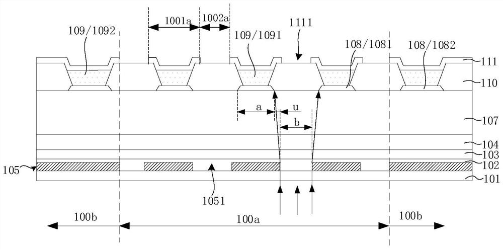
[0003] Embodiments of the present invention provide a display panel and a display device to solve the problem of the existing display panel and display device. When the infrared laser is irradiated from the back of the display panel to the photosensitive area, the cathode layers located in the light-transmitting area and the pixel area are all irradiated by the laser. A technical problem that affects the normal display of the photosensitive area

Method used

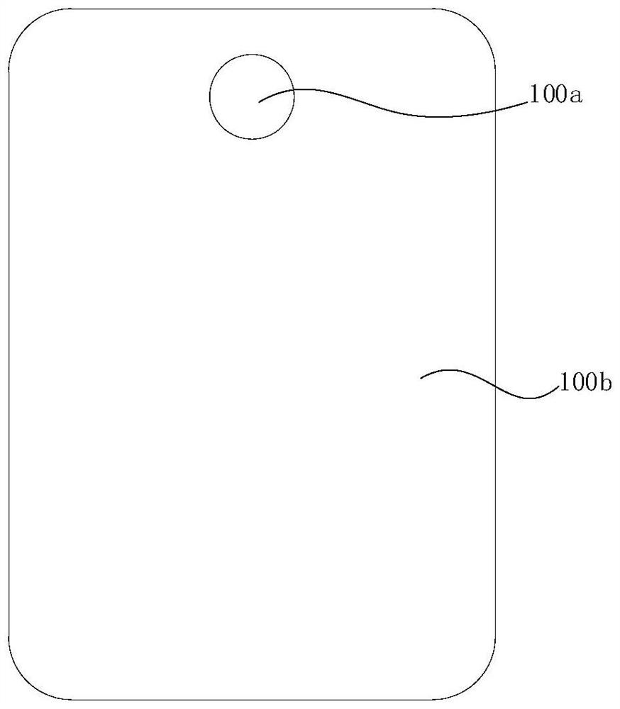
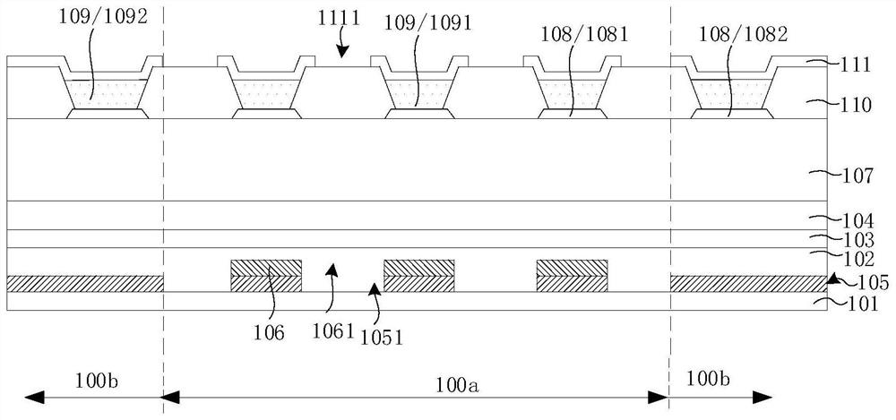

Image

  • Display panel and display device
  • Display panel and display device
  • Display panel and display device

Examples


Embodiment Construction

[0057] The technical solutions in the embodiments of the present invention will be clearly and completely described below with reference to the accompanying drawings in the embodiments of the present invention. Obviously, the described embodiments are only a part of the embodiments of the present invention, rather than all the embodiments. Based on the embodiments of the present invention, all other embodiments obtained by those skilled in the art without creative efforts shall fall within the protection scope of the present invention. In addition, it should be understood that the specific embodiments described herein are only used to illustrate and explain the present invention, but not to limit the present invention. In the present invention, unless otherwise stated, the directional words such as "upper" and "lower" generally refer to the upper and lower parts of the device in actual use or working state, specifically the direction of the drawing in the accompanying drawings....


PUM

PropertyMeasurementUnit
Thicknessaaaaaaaaaa
Thicknessaaaaaaaaaa

Abstract

The invention discloses a display panel and a display device.The display panel comprises a first display area, a second display area, a first substrate, a first light shielding layer, a second light shielding layer, a first electrode layer, a light emitting layer and a second electrode layer; the second electrode layer is provided with a light-transmitting opening between at least part of adjacent first sub-pixels in the first display area; the first shading layer is provided with a first opening corresponding to the light-transmitting opening in the first display area, and the second shading layer is provided with a second opening corresponding to the light-transmitting opening in the first display area. According to the invention, the second light shielding layer is arranged on the basis of the first light shielding layer, so that the overall thickness of the light shielding layer is increased equivalently, the part of the second electrode layer corresponding to the first sub-pixel is prevented from being fallen off by laser, and the laser precision and the light transmittance of the first display area are improved.

Description

technical field [0001] The present invention relates to the field of display technology, and in particular, to a display panel and a display device. Background technique [0002] For an AMOLED (Active-matrix organic light-emitting diode) display panel, how to improve the light transmittance of the photosensitive area of ​​the display panel has always been a difficult problem. One method currently adopted is to adopt the patterned design of the cathode layer in the photosensitive area. The photosensitive area includes a pixel area and a light-transmitting area. The pixel area is used to set light-emitting pixels, and the light-transmitting area is used to transmit light. The cathode layer in the light-transmitting area can improve the transmittance of the light-transmitting area. When the infrared laser is irradiated from the back of the display panel to the photosensitive area, the film below the cathode layer has almost no absorption of the infrared laser, resulting in not ...

Claims


Application Information

Patent Timeline
IPC IPC(8): H01L51/52H01L27/32
CPCH10K59/60H10K59/12H10K50/828H10K50/86
Inventor 蔡华堂
Owner WUHAN CHINA STAR OPTOELECTRONICS SEMICON DISPLAY TECH CO LTD
Learn More