
Electric water valve and application of electric water valve on electric appliance

A water valve and electric technology, applied in the field of solenoid valves, can solve the problems of easy rusting of metal parts, poor opening or closing effect of electric water valves, etc., and achieve the effects of simple assembly, high transmission efficiency, and avoidance of rust.

Pending Publication Date: 2022-07-29
三桥惠(佛山)新材料有限公司 +1
View PDF0 Cites 0 Cited by
  • Summary
  • Abstract
  • Description
  • Claims
  • Application Information

AI Technical Summary

Problems solved by technology

[0003] The purpose of the present invention is to propose an electric water valve and the application of the electric water valve on electrical appliances, aiming to solve the technical problems in the prior art that the opening or closing effect of the electric water valve is poor and the internal metal parts are easy to rust

Method used


Image

  • Electric water valve and application of electric water valve on electric appliance
  • Electric water valve and application of electric water valve on electric appliance
  • Electric water valve and application of electric water valve on electric appliance

Examples


Embodiment Construction

[0050] The technical solutions in the embodiments of the present invention will be clearly and completely described below with reference to the accompanying drawings in the embodiments of the present invention. Obviously, the described embodiments are only a part of the embodiments of the present invention, not all of the embodiments. Based on the embodiments of the present invention, all other embodiments obtained by those of ordinary skill in the art without creative efforts shall fall within the protection scope of the present invention.

[0051] It should be noted that if there are directional indications (such as up, down, left, right, front, back, etc.) involved in the embodiments of the present invention, the directional indications are only used to explain a certain posture (as shown in the accompanying drawings). If the specific posture changes, the directional indication also changes accordingly.

[0052] In addition, if there are descriptions involving "first", "sec...


PUM


Abstract

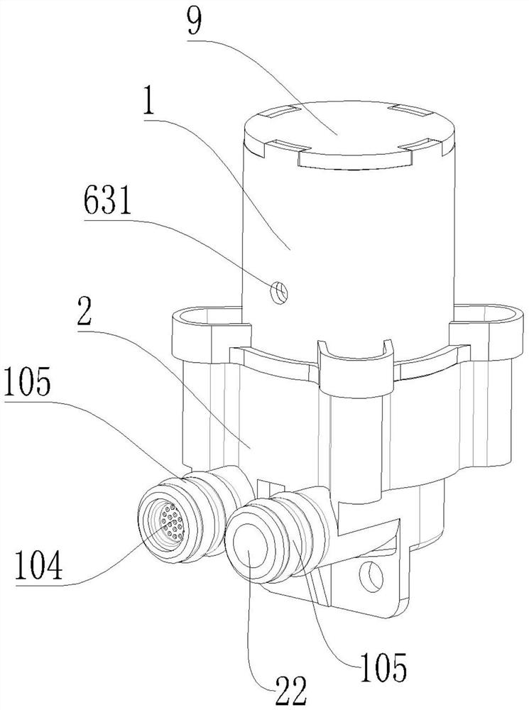
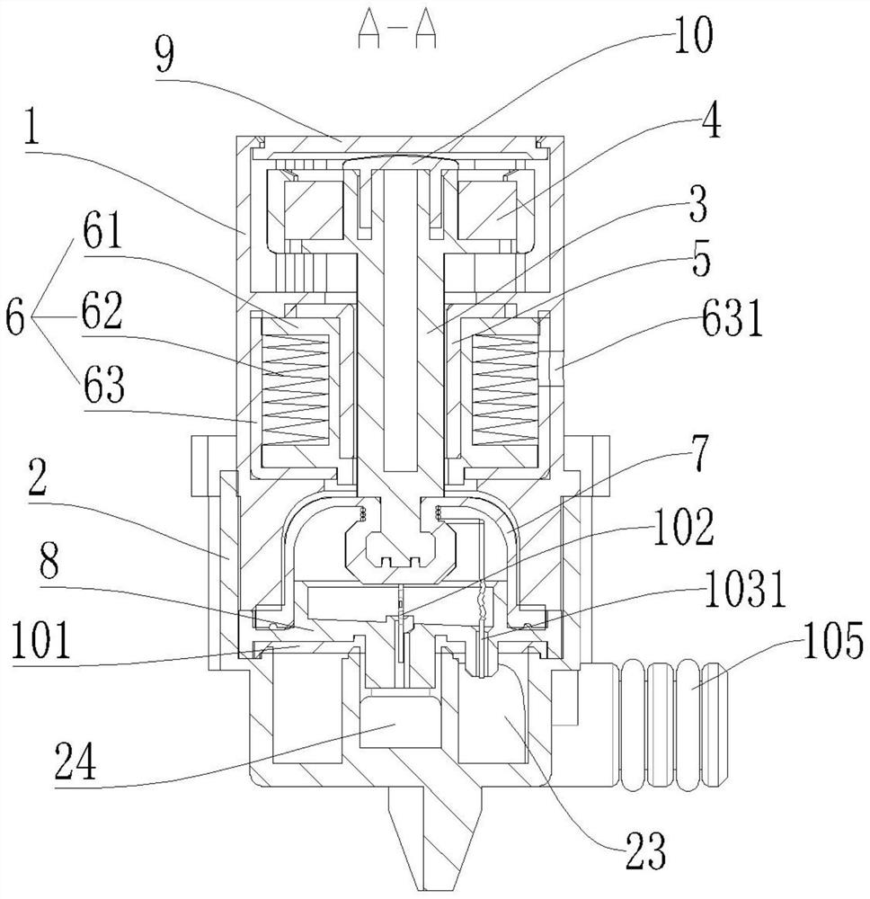
The invention relates to the technical field of electromagnetic valves, in particular to an electric water valve and application of the electric water valve to an electric appliance, comprising a shell, a lower seat, a fixing frame, a permanent magnet, a magnetic core, a coil assembly, sealing silica gel and a lower cover plate; the coil assembly is arranged in the shell and arranged on the magnetic core in a sleeving mode, the permanent magnet is installed on the fixing frame, and the fixing frame is movably arranged on the magnetic core in an inserted mode. The lower base is installed at the lower end of the shell and provided with a water inlet and a water outlet, the lower cover plate is located in the lower base and located at an opening in the lower end of the shell, and the lower cover plate is provided with a water inlet hole and a water outlet hole; the sealing silica gel is arranged at the lower end of the fixing frame and located over the water inlet hole and the water outlet hole, a water inlet cavity and a water outlet cavity which are separated from each other are formed in the lower base, the water inlet cavity is communicated with the water inlet hole and the water inlet hole, and the water outlet cavity is communicated with the water outlet hole and the water outlet hole. The fixing frame is reset through the permanent magnet, force transmission is more directional, and therefore the opening or closing effect of the electric water valve is guaranteed, and the force transmission efficiency is higher.

Description

technical field [0001] The invention relates to the technical field of solenoid valves, in particular to an electric water valve and the application of the electric water valve in electrical appliances. Background technique [0002] When the existing electric water valve is opened, the coil is energized, and the moving iron core overcomes the elastic force of the spring to move away from the water inlet under the action of electromagnetic force, driving the plugging head away from the water inlet; and the electric water valve needs to be closed. When the power is off, the coil is powered off, and the moving iron core approaches the water inlet under the action of the spring force, so that the plugging head blocks the water inlet. This kind of structure needs to rely on the spring for reset, and the spring is formed by the spiral coil of the metal strip, which is non-directional when transmitting the force, and the elastic force is relatively scattered, so the opening or clos...

Claims


Application Information

Patent Timeline
Patent Type & Authority Applications(China)
IPC IPC(8): F16K7/12F16K31/08F16K31/06B08B1/00B01D35/06A47L15/42A47L11/40A47L9/00A47J31/46D06F73/00D06F39/08
CPCF16K7/12F16K31/082F16K31/0675B01D35/06A47L15/4214A47L11/408A47L9/00A47J31/461D06F73/00D06F39/088B01D2201/167B01D2201/34B08B1/10
Inventor 龙克文
Owner 三桥惠(佛山)新材料有限公司
Learn More