Interstage air exhaust backflow gravity compressed air energy storage system and energy storage method

A technology of compressed air energy storage and air return, applied in piston pumps, steam engine devices, liquid variable capacity machines, etc., can solve problems such as output power drop, operating efficiency drop, and operating power consumption increase.

Active Publication Date: 2022-07-29
XIAN THERMAL POWER RES INST CO LTD +2
View PDF6 Cites 0 Cited by
  • Summary
  • Abstract
  • Description
  • Claims
  • Application Information

AI Technical Summary

Problems solved by technology

Specifically, as the inflation process progresses, the gas storage pressure in the gas storage device will gradually increase, so the air compressor is required to continuously increase the discharge pressure to meet the intake pressure requirements, resulting in the air compressor operating outside the design condition , the operating efficiency decreases and the operating power consumption increases, thereby limiting the improvement of the energy storage efficiency of the system; similarly, with the progress of the deflation process, the gas storage pressure in the gas storage device gradually decreases, so the air inlet pressure of the air expander gradually decreases , causing the air expander to deviate from the design operating conditions, resulting in a decrease in operating efficiency and output power, which in turn limits the improvement of the energy storage efficiency of the system

Method used


Image

  • Interstage air exhaust backflow gravity compressed air energy storage system and energy storage method
  • Interstage air exhaust backflow gravity compressed air energy storage system and energy storage method
  • Interstage air exhaust backflow gravity compressed air energy storage system and energy storage method

Examples


Embodiment Construction

[0032] The following describes in detail the embodiments of the present application, examples of which are illustrated in the accompanying drawings, wherein the same or similar reference numerals refer to the same or similar elements or elements having the same or similar functions throughout. The embodiments described below with reference to the accompanying drawings are exemplary and are only used to explain the present application, but should not be construed as a limitation on the present application. On the contrary, the embodiments of the present application include all changes, modifications and equivalents falling within the spirit and scope of the appended claims.

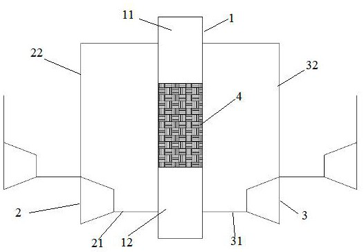
[0033] figure 1 It is a schematic structural diagram of an inter-stage suction and reflux gravity compressed air energy storage system proposed in an embodiment of the present application.

[0034] see figure 1 , an interstage pumping and returning gravity compressed air energy storage system, comprising...


PUM


Abstract

The invention provides an interstage air exhaust backflow gravity compressed air energy storage system and method.The energy storage system comprises a closed air cavity, multiple stages of compressor units connected in series and multiple stages of expansion units connected in series, a gravity plunger is movably inserted into the closed air cavity, and the gravity plunger is connected with the closed air cavity in a sealed mode; the closed air cavity is divided into an upper air cavity and a lower air cavity through a gravity plunger, the multi-stage compressor units connected in series are connected with the lower air cavity through an energy storage pipeline, and middle-stage air suction ports of the multi-stage compressor units connected in series are connected with the upper air cavity through an air suction pipeline; the multiple stages of expansion units connected in series are connected with the lower air cavity through energy release pipelines, middle-stage exhaust ports of the multiple stages of expansion units connected in series are connected with the upper air cavity through exhaust pipelines, and adjusting valves are arranged on the exhaust pipelines. Constant pressure of the air storage device in the inflation and deflation process can be achieved, then the operation efficiency of the air compressor and the expansion machine is improved, and the energy storage efficiency of the system is improved.

Description

technical field [0001] The present application relates to the technical field of electrical energy storage, and in particular, to an interstage extraction and return gravity compressed air energy storage system and an energy storage method. Background technique [0002] Energy storage, especially the storage of electric energy, is of great significance to the optimization of energy structure and the regulation of power grid operation. The compressed air energy storage system is a new type of large-scale energy storage technology. In the gas storage device; when the electrical load of the power system reaches the peak, the gas storage device releases the stored compressed air, expands in the turboexpander to do work and drives the generator to generate electricity; according to the above principles, the compressed air energy storage system can Complete the conversion of electrical energy-air potential energy-electrical energy. [0003] Conventional compressed air energy sto...

Claims


Application Information

Patent Timeline
Patent Type & Authority Applications(China)
IPC IPC(8): F01K27/00F04B41/02F04B41/06F04B35/04F03G3/00
CPCF01K27/00F04B41/02F04B41/06F04B35/04F03G3/00Y02E60/16
Inventor 文军梅生伟王月明薛小代张学林李阳赵瀚辰杨成龙王亚洲
Owner XIAN THERMAL POWER RES INST CO LTD
Why Eureka
Try Eureka