Workpiece unit, curved-surface canopy grid structure and mounting method of curved-surface canopy grid structure
A technology of grid structure and installation method, which is applied in the direction of building structure, building material processing, construction, etc., can solve the problems of low installation efficiency and low construction fault tolerance rate, and achieve the effect of improving installation efficiency and construction fault tolerance rate
- Summary
- Abstract
- Description
- Claims
- Application Information
AI Technical Summary
Problems solved by technology
Method used
Image


Examples
Embodiment 1
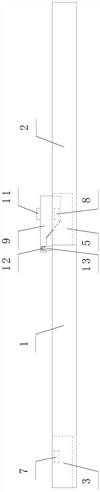
[0045] refer to Figure 1-Figure 2 As shown, this embodiment provides a product unit, including:
[0046] A first body 1 and a second body 2, the first body 1 is in contact with the second body 2, the first body 1 is provided with a first groove 3 and a first plug component 4, the The second body 2 is provided with a second groove 5 and a second plug assembly 6, and a plurality of slots 7 are provided on the side walls of the first groove 3 and the second groove 5;
[0047] The first plug assembly 4 includes a rotating unit and two plug pins 8. The rotating unit is connected to the first body 1. The plug pins 8 are adapted to the sockets 7. When the angle between the first body 1 and the second body 2 is determined, the first body 1 and / or the second body 2 are rotated so that the plug 8 is inserted into the second groove 5 inside the other slot 7.
[0048] The first body 1 is connected with the second body 2, and a curved surface is formed by adjusting the angle between th...
Embodiment 2
[0064] This embodiment provides a curved canopy grille structure, which includes a plurality of product units in the first embodiment, the plurality of product units are connected in sequence to form a curved portion, and one of the two adjacent product units is The second plug assembly 6 of the production unit is matched with the first groove 3 of the other production unit.
[0065] The curved canopy structure is formed by the formed curved part, and the curved surface with different degrees of curvature can be formed by adjusting the angle between the parts units, which makes the on-site construction more flexible;
[0066] Preferably, refer to image 3 As shown, the first body 1 and the second body 2 are connected straightly, and the second groove 5 is only provided with a groove at a straight angle, through which the first body 1 and the second body 2 can be connected to form a straight portion , thus forming a plane at the edge of the curved canopy.
[0067] In one of t...
Embodiment 3
[0070] This embodiment provides a method for installing a curved canopy grille structure, which is used to install the curved canopy grille structure in the second embodiment, including the following steps:
[0071] S1: Abut the first body 1 with the second body 2, so that the first plug assembly 4 is aligned with the second groove 5;
[0072] S2: According to the requirements, insert the pin 8 into the slot 7 corresponding to the second groove 5, so that the angle between the first body 1 and the second body 2 is different;
[0073] S3: welding along the abutment of the first body 1 and the second body 2;
[0074] S4: Weld cover plates on the first body 1 and the second body 2 to cover the first plug-in assembly 4;
[0075] S5: Align the second plug assembly 6 of the second body 2 in step S4 with the first groove 3 on the first body 1 in the other product unit, and adjust the first body 1 and the second body according to requirements 2, weld along the abutment of the first ...
PUM
 Abstract
Description
Claims
Application Information
 - R&D
- Intellectual Property
- Life Sciences
- Materials
- Tech Scout
- Unparalleled Data Quality
- Higher Quality Content
- 60% Fewer Hallucinations
Browse by: Latest US Patents, China's latest patents, Technical Efficacy Thesaurus, Application Domain, Technology Topic, Popular Technical Reports.
© 2025 PatSnap. All rights reserved.Legal|Privacy policy|Modern Slavery Act Transparency Statement|Sitemap|About US| Contact US: help@patsnap.com