
Expansion sleeve type turning and grinding mandrel clamp

A technology of expanding sleeves and turning and grinding, which is applied in the direction of expanding the mandrel and grinding the workpiece support, which can solve the problems of complex positioning, connection and adjustment of the fixture and the processing machine tool, reduce the overall precision of the parts, and the small application range of the device. Good processing effect, improved precision and simple structure

Inactive Publication Date: 2022-07-29
ZHANGQIU HAILI MACHINERY MFG CO LTD
View PDF7 Cites 2 Cited by
  • Summary
  • Abstract
  • Description
  • Claims
  • Application Information

AI Technical Summary

Problems solved by technology

[0004] In actual production, many parts with internal splines (internal teeth) need to be turned and ground after processing the internal splines (internal teeth), but because the technical requirements are based on the large diameter of the internal splines (internal teeth) Or the tooth side, when using other shapes and surfaces as the basis for processing, there must be a transformation of the basis, which reduces the overall accuracy of the part, so the basis for processing needs to be consistent with the standard for technical requirements
At the same time, when the parts are produced in small batches or individually, those fixtures with complex structures will inevitably increase the cost. At the same time, the positioning, connection and adjustment of the fixtures and processing machine tools are complicated, the processing cycle is prolonged, and the production efficiency is reduced.
And most of the expansion sleeve fixtures can only be applied to the chuck connection lathe, so when the lathe does not have a chuck or when the size of the chuck is not suitable, it cannot work, so that the work efficiency is reduced, and the applicable range of the device is small. low rate

Method used


Image

  • Expansion sleeve type turning and grinding mandrel clamp
  • Expansion sleeve type turning and grinding mandrel clamp
  • Expansion sleeve type turning and grinding mandrel clamp

Examples


Embodiment 1

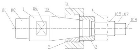
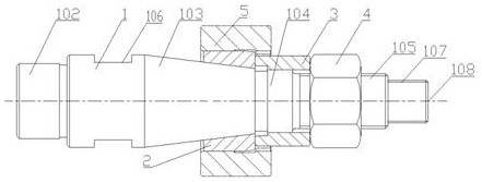
[0053] When in use, the first 102 end of the cylindrical section of the spindle body 1 is directly clamped and positioned on the lathe by a three-jaw chuck, and the second end of the cylindrical section 107 at the other end of the B-type center hole 2 108 is positioned with the rear center of the tailstock. The spring expansion sleeve 2 is installed on the outer side of the taper section 103 of the spindle body 1. The inner hole of the machined part is a smooth hole as the benchmark, and the optical outer circular spring expansion sleeve is selected. The machined part is placed at the spring expansion sleeve 2. The taper is the same as the taper of the taper section 103 of the spindle body 1, and the taper of the taper section 103 and the spring expansion sleeve 2 are both 7:24; one side of the taper section 103 is the guide section 104, the outer side of the guide section 104 The clamping guide sleeve 3 is sleeved, the side of the guide section 104 away from the tapered sectio...

Embodiment 2

[0055] When in use, the workpiece 5 is installed at the spring expansion sleeve 2, the inner hole of the machined part has internal teeth, and when the small diameter 501 of the workpiece 5 with inner teeth is processed as the benchmark, the spring expansion with a smooth outer circle is selected. Then place the B-type center hole 101 at the cylindrical section 1 102 directly on the lathe with the spindle hole center, and the B-type center hole 2 108 at the cylindrical section 2 107 directly on the lathe with the rear center of the tailstock. , the spring expansion sleeve 2 is installed on the outside of the taper section 103 of the spindle body 1, the inner taper of the spring expansion sleeve 2 is the same as the taper of the taper section 103 of the spindle body 1, and the taper of the taper section 103 and the spring expansion sleeve 2 are the same is 7:24; one side of the tapered section 103 is the guide section 104, the outer side of the guide section 104 is sleeved with ...

Embodiment 3

[0057] When in use, the cylindrical section 1 102 is directly clamped and positioned on the lathe with a three-jaw chuck, and the cylindrical section 2 107 is also directly clamped and positioned on the lathe with a three-jaw chuck, and the spring sleeve 2 is installed on the lathe body 1. On the outside of the taper section 103, the inner hole of the machined part is with internal teeth, and the machined part is installed at the spring expansion sleeve 2. When the key side 503 of the machined piece 5 with teeth in the machining inner hole is used as the benchmark, the outer tooth is selected. The round spring expansion sleeve is processed. The inner taper of the spring expansion sleeve 2 is the same as the taper of the taper section 103 of the spindle body 1. The taper of the taper section 103 and the spring expansion sleeve 2 are both 7:24; The side is a guide section 104, the outer side of the guide section 104 is sleeved with the clamping guide sleeve 3, the side of the gui...


PUM


Abstract

The expansion sleeve type turning and grinding mandrel clamp comprises a turning mandrel body and a spring expansion sleeve, the two ends of the turning mandrel body are each provided with a B-type center hole and a cylindrical section, and the turning mandrel body is provided with a taper section, a guide section and a threaded section; the spring expansion sleeve is installed on the outer side of the taper section of the turning mandrel body, and the taper of the interior of the spring expansion sleeve is the same as that of the taper section of the turning mandrel body. One side of the taper section is a guide section, the outer side of the guide section is sleeved with a clamping guide sleeve, one side of the guide section is a threaded section, and the outer side of the threaded section is sleeved with a nut. The device is simple in structure, reliable in precision, low in cost, capable of being replaced on a universal machining tool at any time, convenient to switch and high in machining efficiency; the clamping guide sleeve ensures that the spring expansion sleeve is straightly pressed, the to-be-machined part is clamped, the machining efficiency is improved, and after machining is completed, the workpiece can be easily taken down after the nut is loosened by a small distance, and then operation is repeated.

Description

technical field [0001] The invention relates to the technical field of clamps, in particular to an expanding sleeve type turning and grinding mandrel clamp. Background technique [0002] The sleeve type fixture is a form of fixture that eliminates gaps that should be more and more widely used in the machining industry, especially in gear machining. The traditional expanding-sleeve grinding jig is to make the inner conical surface of the expanding sleeve fit with the outer conical surface of the mandrel of the fixture by pressing the nut, so as to generate an outward tightening force, so as to complete the tightening of the inner hole of the part. . [0003] At present, the general expanding sleeve type car fixtures all use the expanding sleeve to locate the inner hole of the part to be processed. The specific process is to pull the tie rod to open the expanding sleeve, and the expanding sleeve tightens the inner hole of the part, which plays the role of positioning and tigh...

Claims


Application Information

Patent Timeline
Patent Type & Authority Applications(China)
IPC IPC(8): B23B31/40B24B41/06
CPCB23B31/4006B24B41/06
Inventor 陈广福郑学科景慎光
Owner ZHANGQIU HAILI MACHINERY MFG CO LTD
Learn More