Longitudinal bar feeding assembly

A technology of longitudinal bars and components, applied in the direction of online network, household appliances, other household appliances, etc., can solve the problems of large operation volume and low efficiency of workers, and achieve the effect of improving production efficiency, reasonable structure and reducing manual work.

Pending Publication Date: 2022-07-29
中国核工业电机运行技术开发有限公司
View PDF14 Cites 0 Cited by
  • Summary
  • Abstract
  • Description
  • Claims
  • Application Information

AI Technical Summary

Problems solved by technology

[0007] Although the above-mentioned longitudinal rib feeding device can realize automatic feeding of the equipment, it still needs to manually arrange the longitudinal ribs neatly to one side of the main longitudinal rib conveying mechanism and be located at the same level as the production line, and the workload of the workers is still relatively large and the efficiency is low. Low

Method used


Image

  • Longitudinal bar feeding assembly
  • Longitudinal bar feeding assembly
  • Longitudinal bar feeding assembly

Examples


Embodiment 1

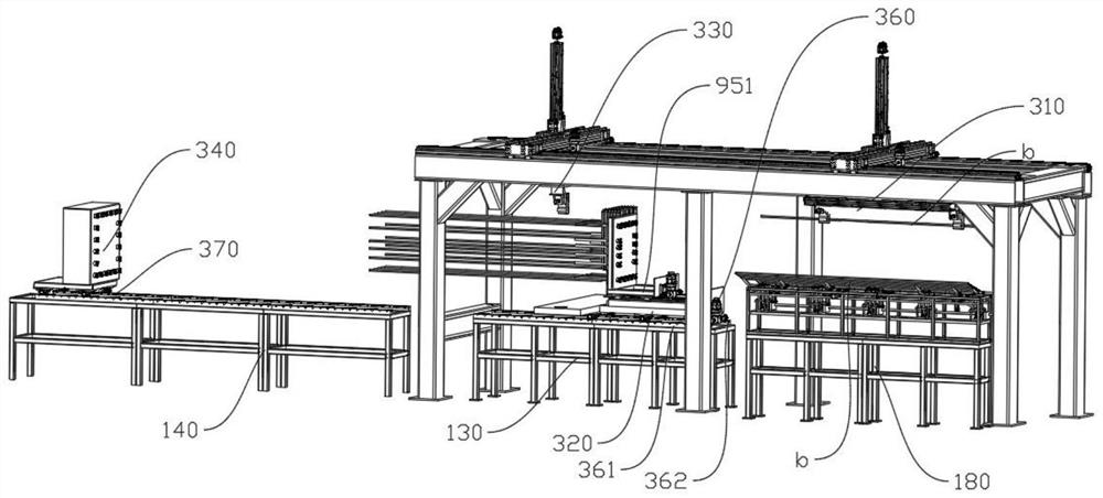
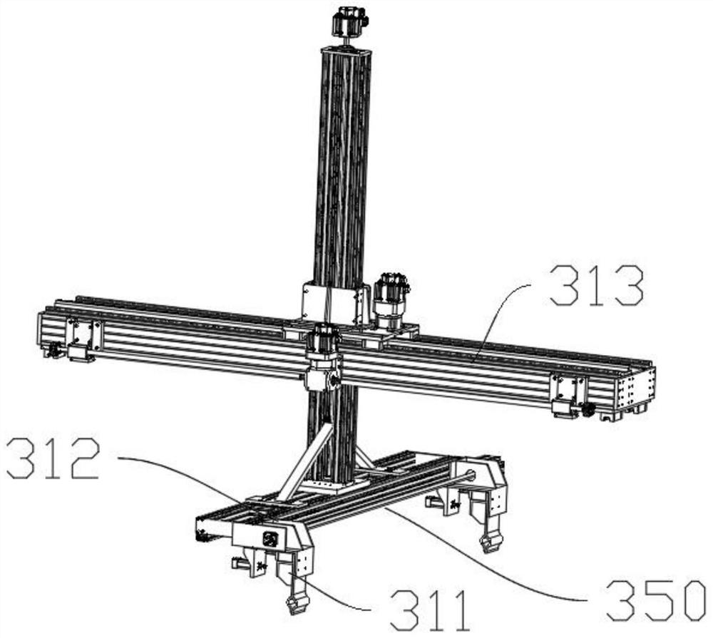
[0042] like Figure 1-12 As shown, the longitudinal rib feeding assembly of Embodiment 1 includes a frame, a longitudinal rib temporary placement rack 180, a longitudinal rib gripper 310 for grabbing the longitudinal rib b on the longitudinal rib temporary placement rack 180, and a longitudinal rib gripper 310 for placing stirrups The carrying platform 320, the longitudinal rib handle 330 and the longitudinal rib head end fixing member 340 of the material box 910, the longitudinal rib gripper 310, the carrying platform 320, the longitudinal rib receiver 330 and the longitudinal rib head end fixing member 340 are in sequence along the transmission direction of the longitudinal rib b. In the arrangement, the longitudinal rib temporary rack 180, the longitudinal rib gripper 310, the bearing platform 320, the longitudinal rib receiver 330 and the longitudinal rib head end fixing member 340 are all connected to the frame.

[0043] The longitudinal rib gripper 310 includes a grippin...

Embodiment 2

[0073] like Figure 13-17 As shown, Embodiment 2 is based on Embodiment 1, and the difference is that: the longitudinal reinforcement handle 330 includes a pick-up manipulator 331, a mechanical base 332 for installing the pick-up manipulator 331, and a driving mechanical base 332 between the bearing platform 320 and the reinforcement cage binding unit The reciprocating mechanical drive assembly 333 and the mechanical base 332 are fixedly connected with the mechanical drive assembly 333 .

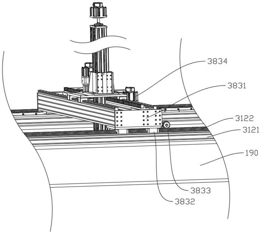
[0074] The mechanical drive assembly 333 includes a fourth drive assembly for driving the manipulator base 312 to move along the x-axis direction. The fourth drive assembly includes a fourth transverse frame 1831 and a fourth guide rail 1121 (with the first The guide rail 3121 is the same guide rail) and the fourth rack 1122 (the same rack as the first rack 3122 ), the fourth slider 1832 fixed on the fourth horizontal frame The fourth gear 1833, the fourth motor 1834 for driving the fourth ...


PUM


Abstract

The invention discloses a longitudinal bar feeding assembly which comprises a rack, a longitudinal bar temporary placing frame, a longitudinal bar gripper used for gripping longitudinal bars on the longitudinal bar temporary placing frame, a bearing platform used for placing stirrup material boxes, a longitudinal bar catcher and a longitudinal bar head end fixing piece. The longitudinal bar gripper, the bearing platform, the longitudinal bar catcher and the longitudinal bar head end fixing piece are sequentially arranged in the longitudinal bar conveying direction, and the longitudinal bar temporary placing frame, the longitudinal bar gripper, the bearing platform, the longitudinal bar catcher and the longitudinal bar head end fixing piece are all connected with the rack. The longitudinal bar feeding assembly is reasonable in structure, the requirement for the position of the longitudinal bar temporary storage frame is low, longitudinal bars on the longitudinal bar temporary storage frame can be fed, manual operation is reduced, and the production efficiency is improved.

Description

technical field [0001] The invention relates to a feeding assembly, in particular to a longitudinal rib feeding assembly. Background technique [0002] In engineering construction projects, the binding and forming of the reinforcement cage is an important link. At present, the binding of the reinforcement cage is manually loaded, especially the long longitudinal reinforcement requires two people to load the material, which is time-consuming and labor-intensive. [0003] In the prior art, a steel cage welding production line as described in CN113967807A includes a longitudinal rib feeding device installed on the main frame, and the longitudinal rib feeding device is used to transport the longitudinal ribs to the operation area; [0004] The longitudinal rib feeding device includes: [0005] The longitudinal rib main conveying mechanism is arranged on the side of the main frame away from the stirrup feeding device, and can clamp and drive the longitudinal rib to move along th...

Claims


Application Information

Patent Timeline
IPC IPC(8): B21F27/08B21F27/20B21F23/00
CPCB21F27/08B21F27/20B21F27/121B21F23/005
Inventor 高飞刘志民李建明
Owner 中国核工业电机运行技术开发有限公司
Why Eureka
Try Eureka