Device for replacing upper carrier roller
A technology of rollers and pallets, applied in the direction of lifting devices, crowbars, etc., can solve the problems of easily damaged tapes, increase the difficulty of replacement, and labor intensity of workers, and achieve the effect of preventing damage to tapes and increasing the contact area
- Summary
- Abstract
- Description
- Claims
- Application Information
AI Technical Summary
Problems solved by technology
Method used
Image

Examples
Embodiment 1
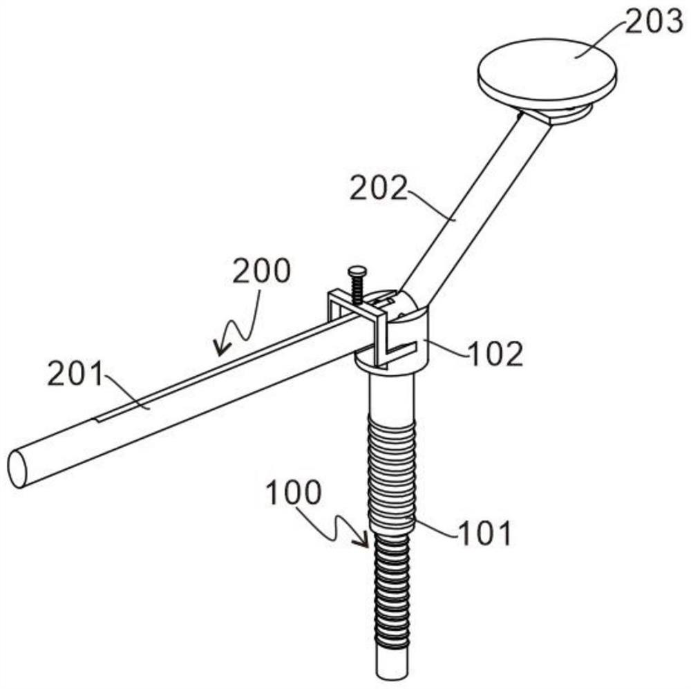
[0027] refer to figure 1 , which is the first embodiment of the present invention. This embodiment provides a device for replacing an upper roller, which includes a support assembly 100 and a tilt rod assembly 200. The support assembly 100 includes a support rod 101 and a connecting seat 102. The connecting seat 102 rotates Connected to the top of the support rod 101, the connecting seat 102 can rotate around the support rod 101, thereby driving the rocker assembly 200 on it to rotate around the support rod 101; the rocker assembly 200 includes a pressure lever handle 201, a support arm 202 and a support plate 203 , the pressure lever handle 201 is connected with the support arm 202, the two have a certain angle, the support plate 203 is arranged on the top of the support arm 202, the rocking rod assembly 200 is rotatably installed in the connecting seat 102, and the rocking rod assembly 200 can be installed in the connecting seat 102 Rotate up and down inside, and push down t...
Embodiment 2
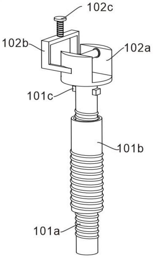
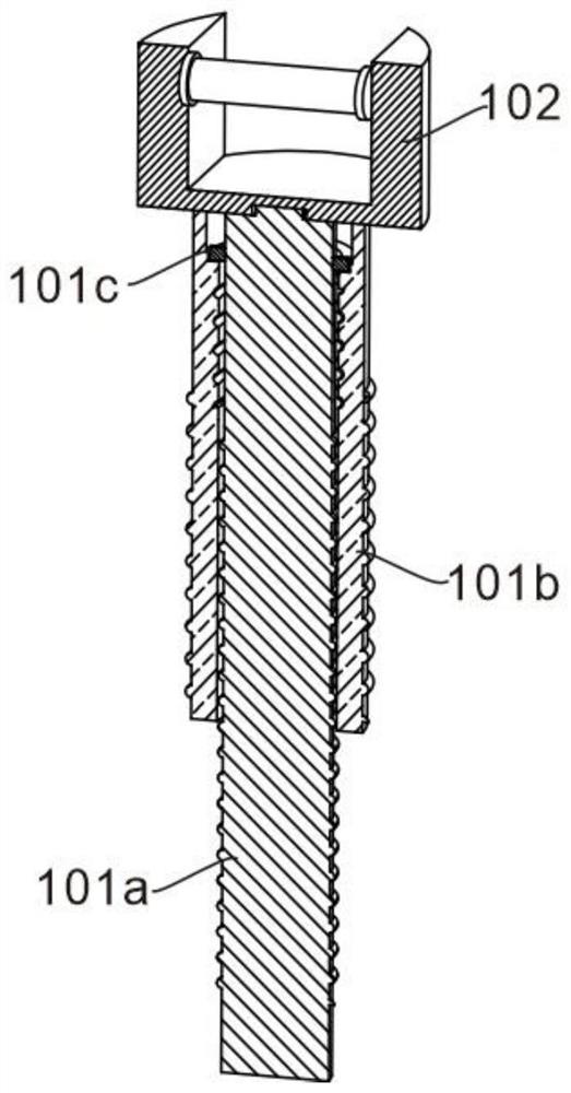
[0031] refer to Figure 1 to Figure 6 , is the second embodiment of the present invention, which differs from the first embodiment in that the support rod 101 includes an inner rod 101a and an outer rod 101b, the outer rod 101b is hollow, the inner rod 101a is sleeved inside the outer rod 101b, The rod 101a can rise along the outer rod 101b, and the connecting seat 102 is rotatably mounted on the top of the inner rod 101a. A thread is provided on the outer side of the bottom end of the inner rod 101a, and a rotating block 101c is provided at the top end of the inner rod 101a. External and internal threads of the outer rod 101b are provided. The internal threads of the outer rod 101b and the threads of the inner rod 101a cooperate with each other. A clamping groove 101d is provided above the inner thread of the outer rod 101b, and the rotating block 101c is located in the clamping groove 101d.
[0032] When the rotating block 101c is located in the slot 101d, the inner thread ...
Embodiment 3
[0040] refer to Figure 1 to Figure 7 , is the third embodiment of the present invention, which is different from the second embodiment in that: the side of the connecting seat 102 close to the pressure lever handle 201 is provided with a grid baffle 102b, and the grid baffle 102b is used to prevent the support plate 203 from After receiving the tape pressure during the ascending process, the pressure lever handle 201 is tilted upward, and the top of the grid baffle 102b is provided with a fixed screw 102c. The fixed screw 102c is used to fix the pressure lever handle 201 when the pressure lever handle 201 is pressed down, so as to keep the pressure lever The depressed state of the handle 201.
[0041] When the inner rod 101a rotates and rises along the outer rod 101b, it simultaneously drives the connecting seat 102 on the top of the inner rod 101a and the tilting rod assembly 200 to rise, and after the support plate 203 is in contact with the tape of the conveyor, the inner ...
PUM
 Abstract
Description
Claims
Application Information
 - R&D
- Intellectual Property
- Life Sciences
- Materials
- Tech Scout
- Unparalleled Data Quality
- Higher Quality Content
- 60% Fewer Hallucinations
Browse by: Latest US Patents, China's latest patents, Technical Efficacy Thesaurus, Application Domain, Technology Topic, Popular Technical Reports.
© 2025 PatSnap. All rights reserved.Legal|Privacy policy|Modern Slavery Act Transparency Statement|Sitemap|About US| Contact US: help@patsnap.com