
Building decoration curtain wall steel structure framework welding manufacturing device

A technology for building decoration and manufacturing equipment, applied in welding equipment, auxiliary equipment, auxiliary welding equipment, etc., can solve the problems of skeleton stress, undercut, weld cracking, etc., to improve welding accuracy, prevent offset, and weld efficiency. high effect

Active Publication Date: 2022-07-26
JIANGSU HAIDEMAN BUILDING MATERIALS IND
View PDF9 Cites 2 Cited by
  • Summary
  • Abstract
  • Description
  • Claims
  • Application Information

AI Technical Summary

Problems solved by technology

[0005] The above solution still has the following problems: 1. When the curtain wall skeleton welding equipment welds the vertical and horizontal skeletons, it only snaps the skeletons together and puts them on the longitudinal support blocks. Although it plays a supporting role, it cannot weld the skeletons. Limit, the curtain wall framework is easy to shake during the welding process, and then defects such as weld offset and undercut appear, resulting in lower welding accuracy of the curtain wall framework
[0006] 2. The skeleton of the curtain wall uses a six-axis welding robot to weld the skeleton, and the operation accuracy is high, which is not suitable for mass production
[0007] 3. After the skeleton is welded, use pneumatic grippers to pull the skeleton from the welding table to the receiving frame, which may cause local stress on the skeleton just after welding, resulting in cracking of the weld seam

Method used


Image

  • Building decoration curtain wall steel structure framework welding manufacturing device
  • Building decoration curtain wall steel structure framework welding manufacturing device
  • Building decoration curtain wall steel structure framework welding manufacturing device

Examples


Embodiment Construction

[0040] The technical solutions in the embodiments of the present invention will be clearly and completely described below with reference to the accompanying drawings in the embodiments of the present invention. Obviously, the described embodiments are only a part of the embodiments of the present invention, but not all of the embodiments. Based on the embodiments of the present invention, all other embodiments obtained by those of ordinary skill in the art without creative efforts shall fall within the protection scope of the present invention.

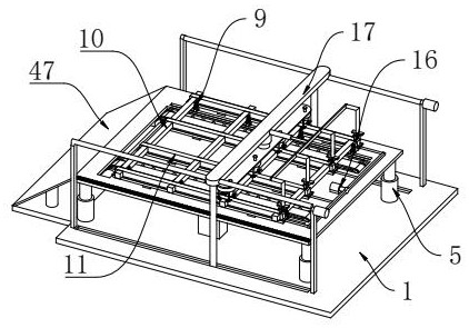
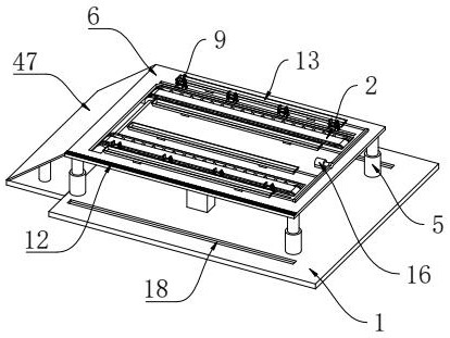
[0041] like Figure 5 As shown in the figure, a welding and manufacturing device for a steel structure frame of a building decoration curtain wall includes an installation base plate 1, the upper surface of the installation base plate 1 is fixedly connected with two groups of parallel transmission mechanisms 2, and the outer wall of the front side transmission mechanism 2 is fixedly installed with a drive motor One 3, the output end o...


PUM


Abstract

The invention relates to the technical field of curtain wall framework welding, and particularly discloses a building decoration curtain wall steel structure framework welding manufacturing device which comprises a mounting bottom plate, two parallel conveying mechanisms are fixedly connected to the upper surface of the mounting bottom plate, and a first driving motor is fixedly mounted on the outer wall of the conveying mechanism on the front side; the output end of the first driving motor is fixedly connected with a transmission rod which drives the two conveying mechanisms to operate at the same time, and four first hydraulic cylinders are fixedly connected to the upper surface of the mounting bottom plate. By arranging the conveying mechanisms, welded longitudinal frameworks and transverse frameworks can be conveyed to the position above a material receiving plate, and the overall transfer function after welding is achieved; the phenomenon that the framework is locally stressed and a welding seam is cracked due to the fact that a pneumatic clamping jaw is adopted to pull the framework is prevented, the limiting mechanism is arranged, the longitudinal framework can be clamped during welding and automatically loosened after welding is completed, the longitudinal framework is prevented from deviating during welding, and the welding precision is improved.

Description

technical field [0001] The invention relates to the technical field of curtain wall skeleton welding, in particular to a welding and manufacturing device for a steel structure skeleton of an architectural decoration curtain wall. Background technique [0002] The architectural decoration curtain wall is composed of panels and supporting structure system, which has the advantages of light weight, flexible design, systematic construction, convenient replacement and maintenance. The existing building curtain wall mostly adopts pre-assembly technology, which is directly transported to the factory after the assembly is completed. Installation at the construction site. [0003] When the factory pre-assembles the architectural decoration curtain wall, the staff mostly use hand-held welding torches to weld the intersections of the curtain wall skeleton one by one, and the welding efficiency is relatively slow. [0004] The Chinese patent discloses an automatic welding equipment app...

Claims


Application Information

Patent Timeline
Patent Type & Authority Applications(China)
IPC IPC(8): B23K37/00B23K37/04
CPCB23K37/00B23K37/0443
Inventor 黄现虎
Owner JIANGSU HAIDEMAN BUILDING MATERIALS IND
Learn More