Crown turbine with margin plate step casing

A technology of edge plates and steps, which is applied in the field of shrouded turbines, can solve the problems of increasing the structural quality of the shroud, the control effect is small, and the blade stress is increased, so as to improve the negative impact, reduce the mixing loss, increase the The effect of flow resistance

Pending Publication Date: 2022-07-22
BEIHANG UNIV
View PDF0 Cites 1 Cited by
  • Summary
  • Abstract
  • Description
  • Claims
  • Application Information

AI Technical Summary

Problems solved by technology

At the same time, increasing the number of comb teeth may increase the quality of the crown structure, thereby increasing the stress on the blade and affecting the life of the blade
Second, the control effect of mixing loss and the performance gain of the turbine stage by only relying on the rounding of the casing downstream of the outlet port is very small

Method used


Image

  • Crown turbine with margin plate step casing
  • Crown turbine with margin plate step casing
  • Crown turbine with margin plate step casing

Examples


Embodiment Construction

[0022] In order to make the purpose, technical solutions and advantages of the embodiments of the present invention clearer, the technical solutions in the embodiments of the present invention will be described clearly and completely below with reference to the accompanying drawings in the embodiments of the present invention.

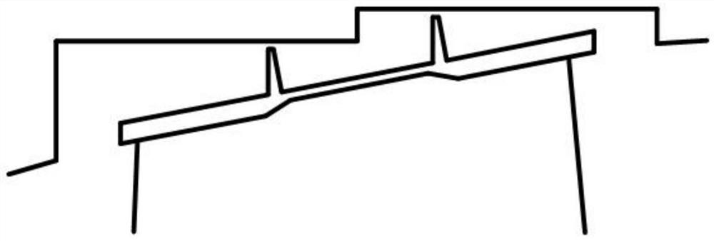
[0023] The research object of the present invention is a single-stage high aspect ratio low pressure crowned turbine. The rotor blade is provided with a double-grate blade crown structure, and the radial tooth tip clearance with the casing is 0.5mm. figure 1 A schematic geometrical representation of the shroud structure on a meridional section is given, this geometry is hereinafter referred to as the "prototype" shroud geometry.

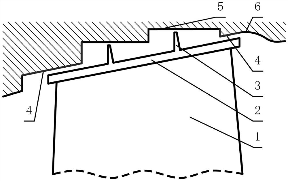
[0024] Starting from reducing the leakage amount and adjusting the momentum distribution of the leakage flow, the present invention modifies the structure of the casing. like figure 2 As shown, the present invention includ...


PUM


Abstract

The shrouded turbine with the margin plate step casing comprises the casing and a hub, blades are evenly installed on the hub along the circumference, the hub and the blades are both installed in the casing, a blade crown is installed on the circumference of the end of each blade, labyrinth teeth are installed on the outer wall of each blade crown, and the labyrinth teeth are installed on the periphery of the end of each blade. Gaps are formed among the blade crown, the comb teeth and the wall surface of the casing at the top of the blade crown, the comb teeth divide the blade crown accommodating cavity into an inlet cavity, a comb tooth cavity and an outlet cavity, margin plate steps are arranged on the wall surfaces of the casing at the tops of the inlet cavity and the outlet cavity, and a smooth curve is connected behind the margin plate step at the top of the outlet cavity for transition.

Description

technical field [0001] The invention belongs to the technical field of turbines, and in particular relates to a crowned turbine with an edge plate stepped casing. Background technique [0002] Losses due to leakage flow at the turbine tip are an important part of the total turbine stage losses in the turbine stage. The shroud sealing structure of the low pressure turbine can restrain the leakage flow and reduce the leakage loss, but the leakage flow still has an important influence on the performance of the turbine stage. Therefore, the use of geometric control methods to minimize the negative effects of the leakage flow of low-pressure turbines with shroud is one of the hot and difficult issues in the research of leakage flow of low-pressure turbine shrouds in recent years. [0003] Controlling the leakage is a direct way to improve the performance of the turbine. In order to reduce the leakage and thus reduce the leakage loss, the most common practice is to increase the n...

Claims


Application Information

Patent Timeline
Patent Type & Authority Applications(China)
IPC IPC(8): F01D5/20F01D25/24F01D11/02
CPCF01D5/20F01D25/24F01D11/02
Inventor 张伟昊黄东铭王宇凡
Owner BEIHANG UNIV
Why Eureka
Try Eureka