
Micro-seismic event accurate positioning method, device and system

A precise positioning and microseismic technology, applied in the direction of seismic signal processing, etc., can solve the problems of microseismic positioning, imaging accuracy is difficult to meet actual needs, and seismic positioning accuracy is not high enough, so as to achieve high signal-to-noise ratio of microseismic signals and simple and efficient positioning method The effect of robust and simple calculation of correlation coefficient

Pending Publication Date: 2022-07-15
温州理工学院
View PDF0 Cites 0 Cited by
  • Summary
  • Abstract
  • Description
  • Claims
  • Application Information

AI Technical Summary

Problems solved by technology

However, in practice, it is found that the imaging methods based on these two sources have some obvious defects, and the imaging accuracy is still difficult to meet the actual needs.
[0003] It was observed that most of the microseisms in the working face occurred near the coal mining face, and a small part occurred on the roof of the roadway on both sides of the working face. These two positions cannot be surrounded by the underground seismic observation system, so the accuracy of earthquake location is not enough high
In general, the current seismic imaging while mining is facing a dilemma: the location of the shearer seismic source can be accurately known, but only interference channel waves with a low signal-to-noise ratio can be obtained when encountering soft coal seams; There are a large number of microseisms in coal seams, and the various seismic phases of microseismic signals have a high signal-to-noise ratio, but it is difficult to accurately locate these microseisms due to the limited layout of the observation system and complex geological conditions

Method used

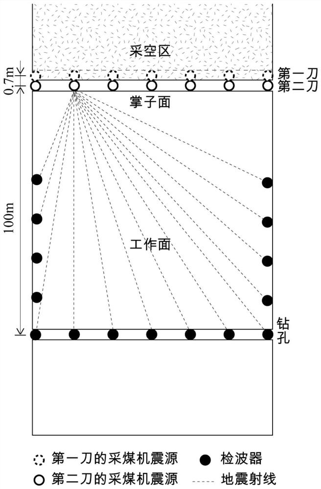
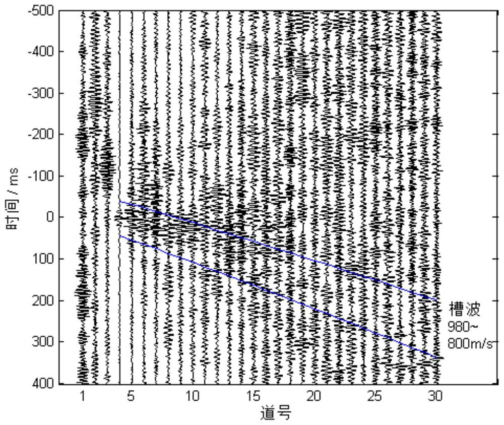

Image

  • Micro-seismic event accurate positioning method, device and system
  • Micro-seismic event accurate positioning method, device and system
  • Micro-seismic event accurate positioning method, device and system

Examples


Embodiment Construction

[0046] In order to make the objectives, technical solutions and advantages of the present application clearer, the technical solutions of the present application will be described in detail below. Obviously, the described embodiments are only a part of the embodiments of the present application, but not all of the embodiments. Based on the examples in this application, all other implementations obtained by those of ordinary skill in the art without creative work fall within the scope of protection of this application.

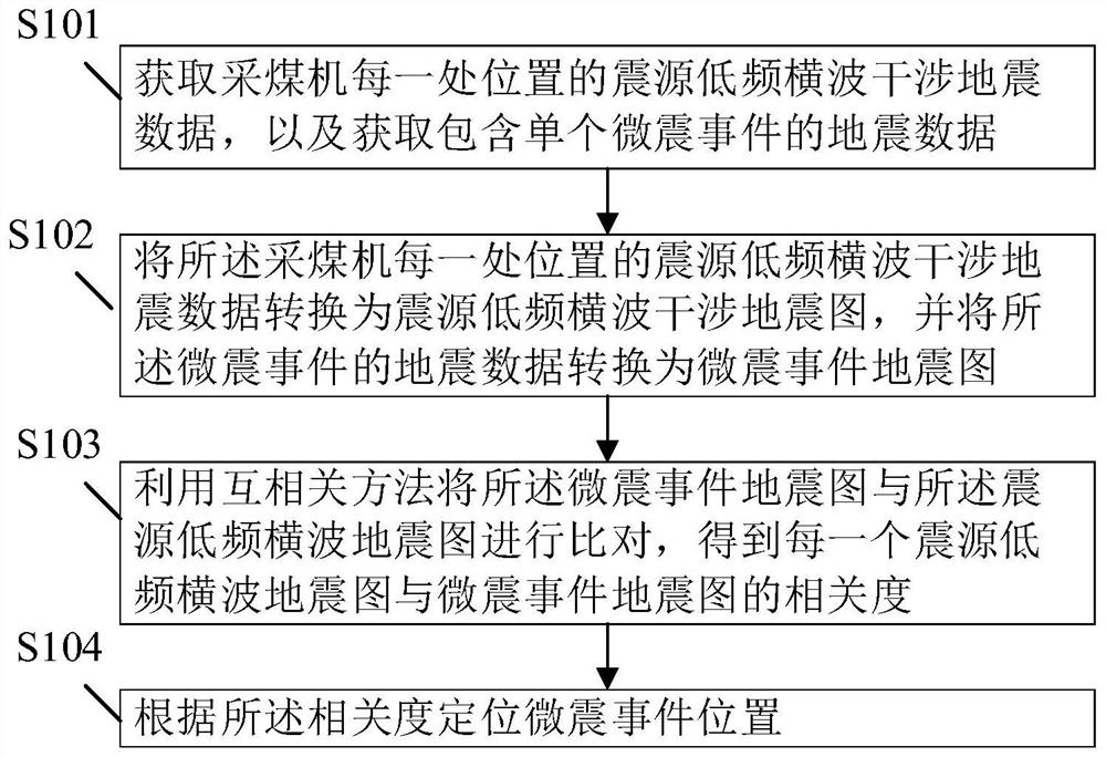
[0047] see figure 1 , figure 1 is a flow chart of a method for accurately locating a microseismic event according to an exemplary embodiment, such as figure 1 As shown, the method for accurately locating microseismic events includes the following steps:

[0048] Step S101, acquiring the hypocenter low-frequency shear wave interference seismic data at each location of the shearer, and acquiring seismic data including a single microseismic event;

[0049] Ste...


PUM


Abstract

The invention relates to a microseismic event accurate positioning method, device and system, and belongs to the technical field of intelligent mining. The method comprises the following steps: acquiring seismic source low-frequency transverse wave interference seismic data of each position of a coal mining machine, and acquiring seismic data including a single microseismic event; converting the seismic source low-frequency transverse wave interference seismic data of each position of the coal mining machine into a seismic source low-frequency transverse wave interference seismic map, and converting the seismic data of the micro-seismic event into a micro-seismic event seismic map; comparing the micro-seismic event seismic map with the seismic source low-frequency transverse wave seismic map by using a cross-correlation method to obtain the correlation degree between each seismic source low-frequency transverse wave seismic map and the micro-seismic event seismic map; and positioning the position of the micro-seismic event according to the correlation degree. The method has the advantages that the position of the coal mining machine seismic source is accurate, the signal-to-noise ratio of the micro-seismic signal is high, and the positioning method is simple and stable.

Description

technical field [0001] The application belongs to the technical field of intelligent mining, and in particular relates to a method, device and system for precise positioning of microseismic events. Background technique [0002] The coal mining face is a frequent site of geological safety accidents in coal mines. The collapsed pillars, faults, old empty areas, and weak roof areas in the strata to be mined will pose potential threats to the staff and mining equipment. If the dangerous structures in these coal formations can be detected in a timely and accurate manner before mining, measures can be taken in advance to prevent the occurrence of geological disasters and reduce the degree of harm of accidents. In addition, in order to realize the unmanned and intelligent coal mining work, high-precision dynamic imaging of the working face is required. At present, the seismic detection of coal mine working face can be divided into two categories according to the source: one is bas...

Claims


Application Information

Patent Timeline
IPC IPC(8): G01V1/28
CPCG01V1/288
Inventor 陆斌李博曲音何畏徐小江谷建晓周向前刘明清
Owner 温州理工学院
Learn More