
Air pressure self-discharging and self-stirring type biological fermentation tank

A biological fermenter and self-stirring technology, applied in the direction of engines, wind turbines, machines/engines, etc., can solve the problems of heavy humidity and inability to ventilate at any time, so as to improve the mobility, increase the mixing reaction area, and increase the force area Effect

Pending Publication Date: 2022-07-15
NANJING INST OF MEASUREMENT & TESTING TECH
View PDF7 Cites 0 Cited by
  • Summary
  • Abstract
  • Description
  • Claims
  • Application Information

AI Technical Summary

Problems solved by technology

[0006] The purpose of the present invention is to provide a kind of air pressure self-releasing self-stirring biological fermenter, to solve the above-mentioned background technology, due to the need for pressure relief, it is also necessary to enter the forced ventilation of the gas, so as to ensure that the oxygen that can supply the organic material for fermentation and biochemical reaction is satisfactory, And it can also take away the heat to prevent the inactivation of microorganisms caused by the high temperature of the pile. Along with the loss of heat, it can also take away a lot of water, but it can't be ventilated at any time, which will easily make the moisture heavier, which is a more troublesome problem.

Method used


Image

  • Air pressure self-discharging and self-stirring type biological fermentation tank
  • Air pressure self-discharging and self-stirring type biological fermentation tank
  • Air pressure self-discharging and self-stirring type biological fermentation tank

Examples


Embodiment Construction

[0037] The technical solutions in the embodiments of the present invention will be clearly and completely described below with reference to the accompanying drawings in the embodiments of the present invention. Obviously, the described embodiments are only a part of the embodiments of the present invention, rather than all the embodiments. Based on the embodiments of the present invention, all other embodiments obtained by those of ordinary skill in the art without creative efforts shall fall within the protection scope of the present invention.

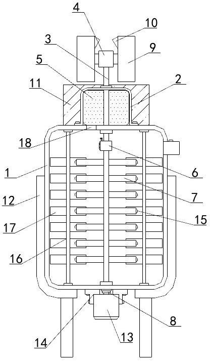
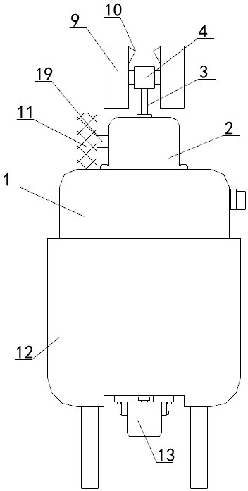
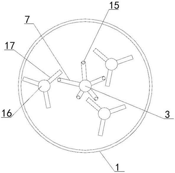
[0038] see Figure 1-5, the present invention provides a technical solution: a pneumatic self-discharging and self-stirring biological fermenter, comprising:

[0039] The tank body 1 is the main outer frame installation structure of the equipment. The outer surface of the tank body 1 is provided with a bracket 12, the top of the tank body 1 is provided with a through cavity 18, and the top of the through cavity 18 is provided with a ...


PUM


Abstract

The invention discloses an air pressure self-discharging and self-stirring type biological fermentation tank which comprises a tank body and an outer frame mounting structure which is a main device, a support is arranged on the outer surface of the tank body, a through cavity is formed in the top end of the tank body, and a recycling box is arranged at the top end of the through cavity; the shell is located at the middle end of the top of the tank body, a discharging pipeline is connected between the shell and the recycling box, and a throttling valve is installed in the discharging pipeline; the functional rod is located in the tank body, one end of the functional rod penetrates through the shell and the interior of the tank body, and a fixing shaft sleeve, a discharging blade, a connecting shaft sleeve, a stirring rod and a mounting shaft sleeve are sequentially arranged on the outer surface of the functional rod from top to bottom. According to the air pressure self-discharging and self-stirring type biological fermentation tank, not only can the stirring regularity in equipment be disrupted and the mixing reaction area be increased, but also a biological material can be extruded and crushed by utilizing the balls, so that the reaction effect of a biological organic fertilizer is further improved.

Description

technical field [0001] The invention relates to the technical field of biological organic fertilizer production, in particular to an air pressure self-discharging and self-stirring biological fermentation tank. Background technique [0002] With the development of genetic engineering, more and more microbial strains are put into industrial production. In the existing microbial industrial production, a large number of microbial fermenters are used for large-scale cultivation. If the assimilation is greater than the dissimilation, the amount of cytoplasm will continue to increase, the volume will increase, and effective metabolites will continue to be generated; microorganisms are under certain physical and chemical conditions, growth and development are normal, and the reproduction rate is also high. High; if one or some environmental conditions change beyond the range that organisms can adapt to, it will inhibit or even kill the organism. [0003] First, for example, the ap...

Claims


Application Information

Patent Timeline
IPC IPC(8): C05F17/90C05F17/964C05F17/979F03D9/20B01D46/10B01D46/56
CPCC05F17/90C05F17/964C05F17/979B01D46/10F03D9/20B01D2258/06
Inventor 李舒陈鸿飞王丽丹
Owner NANJING INST OF MEASUREMENT & TESTING TECH
Learn More