Flow testing platform for testing high-precision ultrasonic flowmeter

An ultrasonic flowmeter and flow testing technology, applied in the direction of testing/calibrating volume flow, etc., can solve the problems of low accuracy, large turbulence, inconsistency, etc., and achieve the effect of convenient adjustment and high adjustment efficiency

Pending Publication Date: 2022-07-12
上海赛腾源研医疗科技有限公司
View PDF0 Cites 0 Cited by
  • Summary
  • Abstract
  • Description
  • Claims
  • Application Information

AI Technical Summary

Problems solved by technology

At present, the flow test platform for ultrasonic flow often has the following problems: 1. The proportional valve is commonly used for adjustment, but the problem with the proportional valve is that it is easy to cause large turbulence at low flow rate, and it is difficult to adjust accurately; 2. The existing system can only Provides one-way flow, requiring reconnection of sensor or tubing each time to measure reverse flow, causing inconsistencies
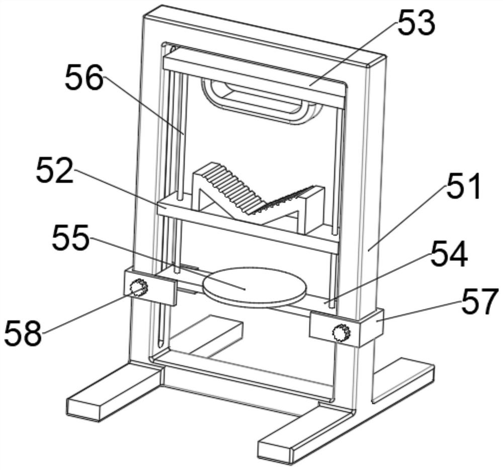
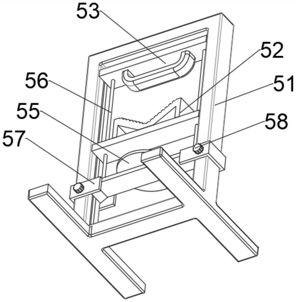
However, there are some other problems in the current flow test platform. First, the pipe gripper is used to solve the problem of the proportional valve. The pipe gripper is used to change the cross-sectional area of ​​the pipeline to achieve flow adjustment, but the current pipe gripper is generally pushed through the thread. The structure realizes the clamping operation, the accuracy is low, and for the high-precision ultrasonic flowmeter, it is necessary to test the measurement effect under different conditions, and a convenient and accurate test method for controlling variables is required

Method used


Image

  • Flow testing platform for testing high-precision ultrasonic flowmeter
  • Flow testing platform for testing high-precision ultrasonic flowmeter
  • Flow testing platform for testing high-precision ultrasonic flowmeter

Examples


Embodiment Construction

[0034] In order to make the purposes, technical solutions and advantages of the disclosed embodiments of the present invention clearer, the technical solutions of the disclosed embodiments of the present invention will be clearly and completely described below with reference to the accompanying drawings of the disclosed embodiments of the present invention. Obviously, the described embodiments are some, but not all, embodiments of the present disclosure. Based on the described embodiments disclosed in the present invention, all other embodiments obtained by those of ordinary skill in the art without creative efforts fall within the scope of protection disclosed in the present invention.

[0035] Unless otherwise defined, technical or scientific terms used in the present disclosure shall have the ordinary meaning as understood by one of ordinary skill in the art to which the present disclosure belongs. The use of "comprising" or "comprising" and similar words in the present dis...


PUM


Abstract

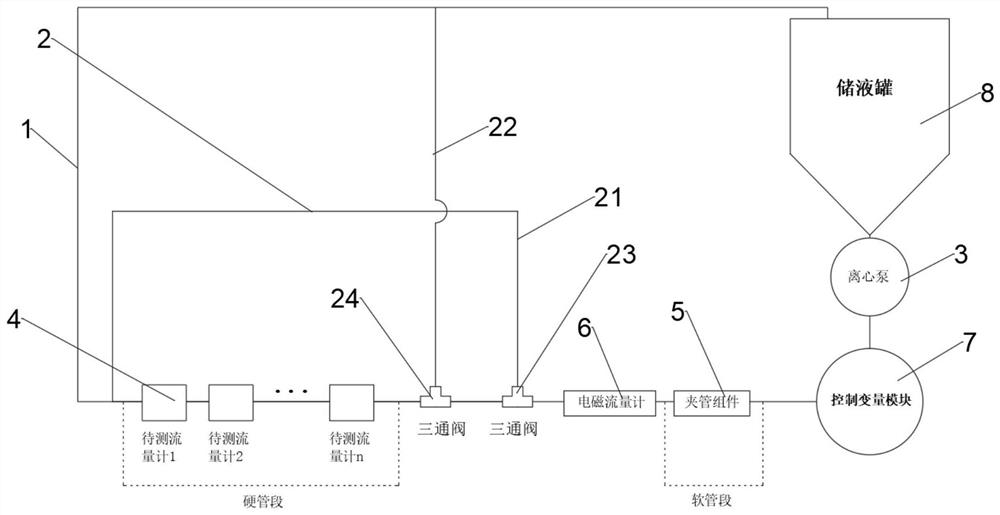
The invention discloses a flow testing platform for testing a high-precision ultrasonic flowmeter, which comprises a main pipeline, a liquid storage tank, an ultrasonic flowmeter, an ultrasonic flowmeter, an ultrasonic flowmeter, a flow meter, a flow meter and an ultrasonic flowmeter, and is characterized in that the main pipeline is a closed pipeline for a medium to pass through and is fixedly connected with the liquid storage tank; a centrifugal pump is fixedly connected to the connecting position of the liquid storage tank and the main pipeline, so that liquid stored in the liquid storage tank can circulate in the main pipeline; the main pipeline is provided with a plurality of to-be-measured flowmeter connecting points and a pipe clamping assembly. An electromagnetic flow meter is fixedly connected to the main pipeline, and the electromagnetic flow meter is arranged between a plurality of to-be-detected flow meter connecting points and the pipe clamping assembly so that the electromagnetic flow meter can accurately detect the flow adjusted by the pipe clamping assembly; the main pipeline is further provided with a flow direction replacing assembly. And the main pipeline is also fixedly connected with a control variable module. Accurate flow testing can be carried out on the high-precision ultrasonic flow meter, meanwhile, the testing efficiency is high, and the measuring effect on the high-precision ultrasonic flow meter is improved in a variable control mode.

Description

technical field [0001] The invention relates to an ultrasonic flowmeter testing device, in particular to a flow testing platform for testing high-precision ultrasonic flowmeters. Background technique [0002] When testing and calibrating flow meters, it is necessary to precisely regulate the flow over a wide range with minimal turbulence to provide an accurate and stable measurement and calibration environment. At present, the flow test platform for ultrasonic flow often has the following problems: First, the proportional valve is commonly used for adjustment, but the problem of the proportional valve is that it is easy to cause large turbulence at low flow, and it is difficult to adjust accurately; Second, the existing system can only Providing unidirectional flow requires reconnecting the sensor or tubing to measure reverse flow each time, creating inconsistencies. Therefore, it is necessary to design a flow test platform for testing high-precision ultrasonic flowmeters f...

Claims


Application Information

Patent Timeline
Patent Type & Authority Applications(China)
IPC IPC(8): G01F25/10
Inventor 徐玲李建朝李晓坤蔡慧玲张宏刚刘宇杰
Owner 上海赛腾源研医疗科技有限公司
Why Eureka
Try Eureka