
Rotation pump working wheel

A technology of working wheels and rotary pumps, applied to pumps, pump components, non-variable pumps, etc., can solve the problems of clumsiness and cumbersome structural design, and achieve the effect of reliable connection

Pending Publication Date: 2022-07-12
KSB AG
View PDF5 Cites 0 Cited by
  • Summary
  • Abstract
  • Description
  • Claims
  • Application Information

AI Technical Summary

Problems solved by technology

This configuration of the fastening by means of an intermediate flange is cumbersome and awkward, since the intermediate flange is not arranged on the shaft opposite to the hub, but is placed at the end of the shaft between the shaft and the impeller. place

Method used


Image

  • Rotation pump working wheel
  • Rotation pump working wheel
  • Rotation pump working wheel

Examples


Embodiment Construction

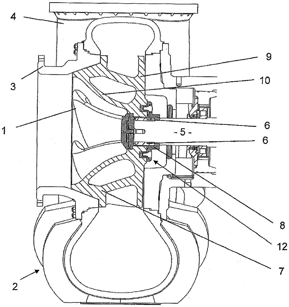
[0044] figure 1 A rotary pump impeller 1 is shown, which is arranged in a housing 2 of the rotary pump. The housing 2 comprises a suction opening 3 through which the supply medium is sucked up and supplied by means of the rotary pump impeller 1 in the direction of the outflow opening 4 and then leaves the rotary pump.

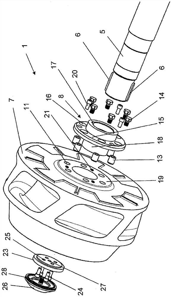
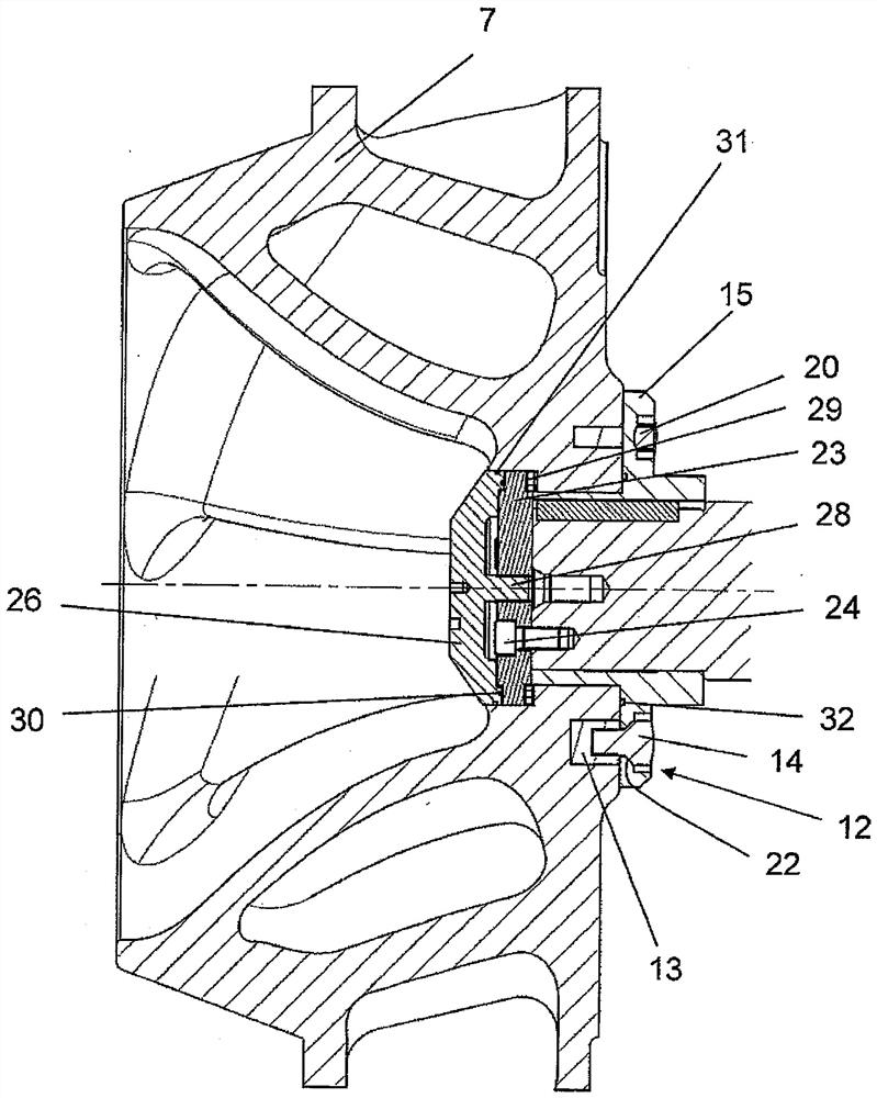
[0045] The rotary pump impeller 1 is arranged on a shaft 5 . The shaft 5 is set in rotation by a motor not shown. In this case, the torque is transmitted via the two flat keys 6 to the metallic hub part 8 and via the entraining element 12 to the non-metallic rotor part 7 of the rotary pump rotor 1 .

[0046] The rotary pump impeller 1 is formed by a non-metallic impeller part 7 and a metallic hub part 8 . In the exemplary embodiment, the non-metallic wheel part 7 is made of a ceramic-plastic-composite material, in which silicon carbide particles are embedded in a polymer matrix.

[0047] The hub 8 is made of a rust-free duplex steel casting with a ferritic-...


PUM


Abstract

The invention relates to a rotary pump impeller (1) having a non-metallic impeller part (7) and a metallic hub part (8) connected to the impeller part (7), which hub part is arranged on a shaft (5), according to the invention there is a releasable connection between the impeller part (7) and the hub part (8).

Description

technical field [0001] The invention relates to a rotary pump impeller having a non-metallic impeller part and a metallic hub connected to the impeller part, the hub being arranged on a shaft. Background technique [0002] The rotary pump impeller, which is formed entirely of metal, is usually fastened to the shaft in such a way that it is pushed with its hub bore onto the shaft end and pressed against the shoulder of the shaft by means of a nut. Such a fastening method is disadvantageous in rotary pump rotors according to the preamble of the invention, since these rotary pump rotors comprise non-metallic rotor parts. Many non-metallic materials, such as polymer castings or plastics, tend to flow under pressure. [0003] DE 44 44 965 A1 describes a rotary pump impeller comprising a non-metallic impeller part and a metallic hub part. The hub is a component that is arranged on the drive shaft and surrounds the drive shaft. The hub is provided with a central receiving openin...

Claims


Application Information

Patent Timeline
Patent Type & Authority Applications(China)
IPC IPC(8): F04D29/22
CPCF04D29/026F04D29/20F04D29/2227F05D2260/30F05D2300/2261F05D2300/6033
Inventor R.克拉梅C.施密特
Owner KSB AG
Learn More