Control method, system and equipment of active filter and medium
A technology of source filter and control method, applied in harmonic reduction device, AC network to reduce harmonic/ripple, frequency selection two-terminal pair network, etc., can solve the problem of high cost of high-power power electronic devices, and achieve The effect of convenience, compensation control delay, and simple principle
- Summary
- Abstract
- Description
- Claims
- Application Information
AI Technical Summary
Benefits of technology
Problems solved by technology
Method used
Image

Examples
Embodiment 1
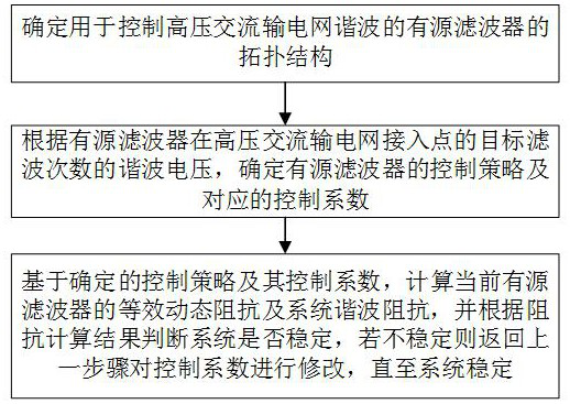
[0047] like figure 1 As shown, the present invention provides a control method of an active filter, comprising the following steps:
[0048] (1) Determine the topology of the active filter used to control the harmonics of the high-voltage AC transmission network.
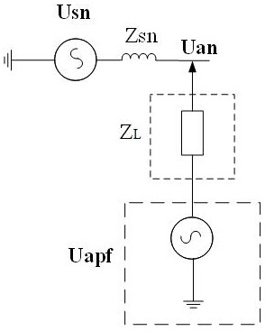
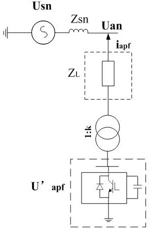
[0049] like figure 2 As shown, the electrical equivalent circuit of the topology structure of the active filter for controlling the harmonics of the high-voltage AC transmission network applicable to this embodiment includes: an equivalent voltage source U apf and the equivalent connection impedance Z L , where the equivalent connection impedance Z L The high-voltage end of the sn is the nth-order background harmonic voltage of the high-voltage AC transmission network, U an is the n-th harmonic voltage of the access point A between the active filter and the high-voltage AC transmission network, Z sn is the equivalent harmonic impedance of the system; the equivalent connection impedance Z L The low-voltage en...
Embodiment 2
[0085] like Figure 4 As shown, the topological structure of the power electronic converter valve used in this embodiment is connected to the high-voltage power grid through the passive filter, and the impedance Z of the passive filter L The corresponding impedance curve is as Figure 5 As shown, it is purely capacitive when the frequency is the lowest, resistive + resistive when the frequency is the highest, and the lowest impedance tuning is 5 times, that is, the absolute value of the impedance is the lowest at 250Hz. The design filtering times are 3 times. Collect the access point voltage u a , the current of the control passive filter and the voltage of the access point differ by 10° in the third time, and the amplitude ratio is 0.1, and the equivalent impedance curve of the active filter is obtained as follows: Image 6 As shown in the figure, when the impedance of the 3rd order is 10∠10°Ω, it can be seen that the impedance curve does not circle the impedance zero poin...
Embodiment 3
[0087] The foregoing Embodiment 1 provides a control method for an active filter, and correspondingly, this embodiment provides a control system for an active filter. The system provided in this embodiment can implement an active filter control method in Embodiment 1, and the system can be implemented by software, hardware, or a combination of software and hardware. For example, the system may include integrated or separate functional modules or functional units to perform corresponding steps in each method of Embodiment 1. Since the system of this embodiment is basically similar to the method embodiment, the description process of this embodiment is relatively simple, and the relevant part may refer to the partial description of Embodiment 1, and the embodiment of the system provided by this embodiment is only illustrative .
[0088] A control system for an active filter provided by this embodiment includes:
[0089] a topology determination module for determining the topol...
PUM
 Abstract
Description
Claims
Application Information
 - R&D
- Intellectual Property
- Life Sciences
- Materials
- Tech Scout
- Unparalleled Data Quality
- Higher Quality Content
- 60% Fewer Hallucinations
Browse by: Latest US Patents, China's latest patents, Technical Efficacy Thesaurus, Application Domain, Technology Topic, Popular Technical Reports.
© 2025 PatSnap. All rights reserved.Legal|Privacy policy|Modern Slavery Act Transparency Statement|Sitemap|About US| Contact US: help@patsnap.com