High-temperature rotor rotary sealing structure, mounting method and compensation pressure control method

A rotary sealing and rotor technology, applied in furnace control devices, furnace components, furnaces, etc., can solve problems such as leakage of flue gas and poor sealing effect, and achieve the effect of avoiding leakage, long service life and avoiding direct failure.

Active Publication Date: 2022-07-08
CHINA ERZHONG GRP DEYANG HEAVY IND
View PDF6 Cites 0 Cited by
  • Summary
  • Abstract
  • Description
  • Claims
  • Application Information

AI Technical Summary

Problems solved by technology

[0005] The purpose of the present invention is: for the rotary sealing mechanism of the rotor system in the prior art, most of them are only axial sealing, and the axial sealing effect still has the problem of leakage of smoke Risk, there is still the problem of poor sealing effect, provide a high-temperature rotor rotary sealing structure, installation method and control method for compensating pressure

Method used


Image

  • High-temperature rotor rotary sealing structure, mounting method and compensation pressure control method
  • High-temperature rotor rotary sealing structure, mounting method and compensation pressure control method
  • High-temperature rotor rotary sealing structure, mounting method and compensation pressure control method

Examples


Embodiment 1

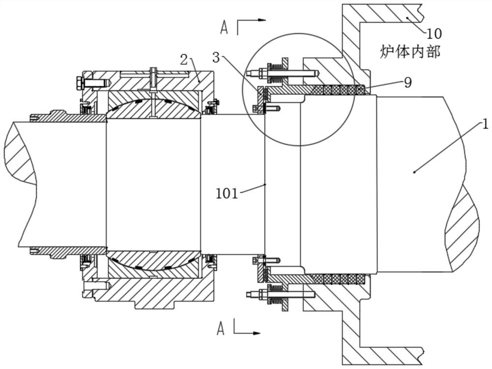
[0089] This embodiment provides a high-temperature rotor rotary sealing structure, which can be referred to Figure 1-4 , including an axial seal 9, a gland 7, an end cover 3, a first radial seal 4 and a second radial seal 13 that are coaxially arranged with the rotor 1 and sleeved on the outside of the rotor 1;

[0090] The axial seal 9 is used to be placed in the gap cavity enclosed between the furnace body 10 and the rotor 1 , and the gland 7 is arranged on the furnace body 10 along the axial direction of the rotor 1 . and the end cover 3, the pressure cover 7 is detachably connected to the furnace body 10 and can press the axial seal 9 along the axial direction of the rotor 1, and the pressure cover 7 is along its axial direction An end face pressing plate 5 is provided at one end away from the axial seal 9, the end face pressing plate 5 is arranged coaxially with the rotor 1, and the first radial seal 4 is arranged on the end face pressing plate 5 and the end face pressin...

Embodiment 2

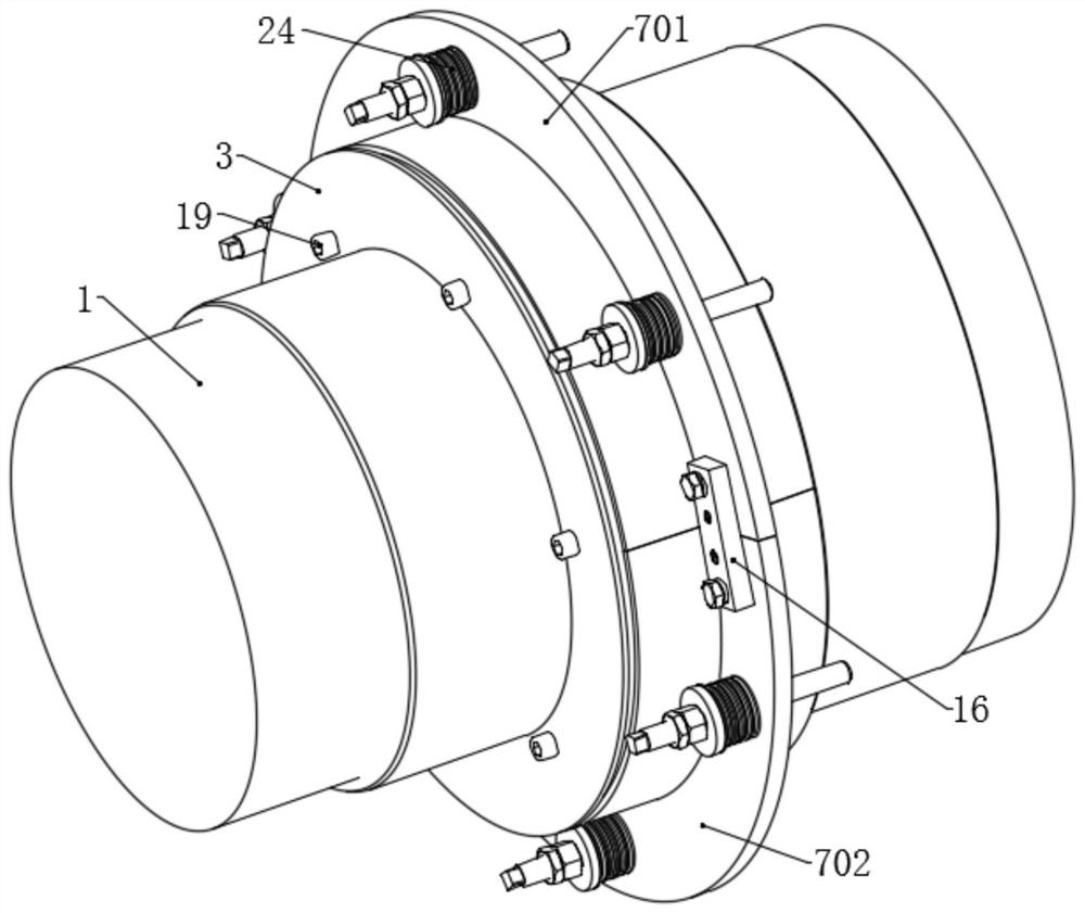
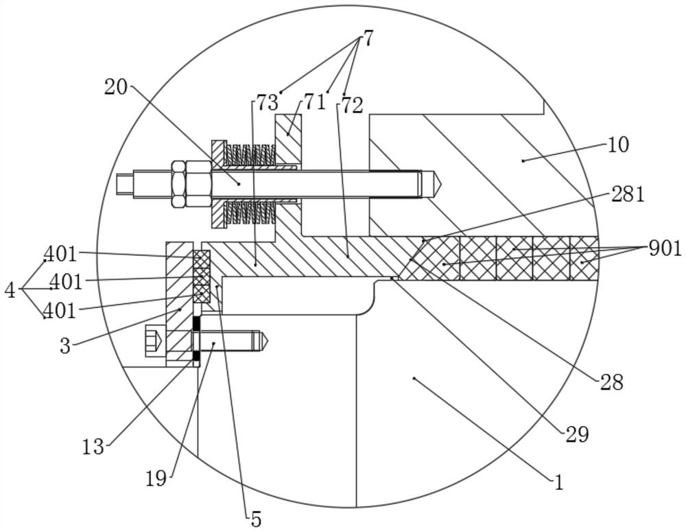
[0103] This embodiment provides a high-temperature rotor rotary sealing structure, see figure 1 and Figure 7-13 , compared with Embodiment 1, the difference is that the connecting part 71 of the gland is connected to the end face of the furnace body 10 through a plurality of the first compensation devices, and the first compensation devices are used as detachable connection furnaces The structure of the body and the gland 7 can also compensate for the pressing effect on the axial seal 9; Guide grooves 27, the telescopic guide grooves 27 are arranged along the circumferential direction of the rotor 1, and a second compensation device is arranged in the telescopic guide grooves 27.

[0104] see Figure 10-13 , the first compensation device includes a screw 20, a locking nut 14, a guide sleeve 22 and a disc spring group 24, the screw 20 is arranged along the axial direction of the rotor 1, the locking nut 14, the guide sleeve 22 and The disc spring groups 24 are all located o...

Embodiment 3

[0110] This embodiment provides a high-temperature rotor rotary sealing structure, see Figure 16-22, which is different from Embodiment 2 in that the structures and arrangements of the first compensation device and the second compensation device are different.

[0111] In this embodiment, as Figure 19-20 As shown, the first compensation device includes a gland hydraulic cylinder 8 and a lock nut 14, the body of the gland hydraulic cylinder 8 is connected to the outside of the furnace body 10, and the gland of the gland hydraulic cylinder 8 The hydraulic rod 81 passes through the connecting portion 71 and is locked by corresponding to the locking nut 14 , and the gland hydraulic rod 81 can drive the connecting portion 71 to move in the axial direction of the rotor 1 . When the gland 7 includes an upper gland 701 and a lower gland 702 , the upper gland 701 and the lower gland 702 are provided with the same number of connecting holes for gland hydraulic rods 81 .

[0112] Com...


PUM


Abstract

The invention relates to a high-temperature rotor rotary sealing structure, an installation method and a compensation pressure control method. The rotary sealing structure of the high-temperature rotor comprises an axial sealing element, a gland, an end cover, a first radial sealing element and a second radial sealing element, wherein the axial sealing element and the rotor are coaxially arranged, and the rotor is sleeved with the axial sealing element. The axial sealing piece is used for being arranged in a gap cavity defined by the furnace body and the rotor, the gland is arranged between the furnace body and the end cover in the axial direction of the rotor, the gland is detachably connected with the furnace body and can extrude the axial sealing piece in the axial direction of the rotor, and an end face pressing plate is arranged at the end, away from the axial sealing piece, of the gland in the axial direction of the gland. The end face pressing plate and the rotor are coaxially arranged, the first radial sealing piece is arranged between the end face pressing plate and the end cover, the second radial sealing piece is arranged between the end cover and the axial step face structure of the rotor, and the end cover is detachably connected with the axial step face structure. The sealing effect is better, and the service life is longer.

Description

technical field [0001] The invention relates to the technical field of mechanical seals, in particular to a high-temperature rotor rotary seal structure, an installation method and a control method for compensating pressure. Background technique [0002] In recent years, with the rapid development of modern industry, the working environment of the rotor system has become increasingly complex, and the working conditions of high temperature and high pressure are not uncommon. In general, the operating temperature of the high temperature rotor is not lower than 480 ℃, and the requirements for the rotor structure are relatively high. The rotary sealing mechanism of the rotor system is one of the key components of the rotating machinery. The sealing performance of the rotor not only affects the production operation, but also relates to production maintenance and environmental protection. The leakage of the high temperature rotor seal will cause energy waste and material loss, and...

Claims


Application Information

Patent Timeline
Patent Type & Authority Applications(China)
IPC IPC(8): F27D99/00F27D19/00
CPCF27D99/0073F27D19/00F27D2019/0028
Inventor 杨闽江浩刘胜涛杨静豪
Owner CHINA ERZHONG GRP DEYANG HEAVY IND
Why Eureka
Try Eureka