Control method of refrigerator

A control method and refrigerator technology, which are applied to household refrigerators, household refrigeration devices, lighting and heating equipment, etc., can solve the problems of easy condensation, inconvenient independent control of ice making, temperature rise, etc., and achieve reliable results.

Pending Publication Date: 2022-07-08
QINGDAO HAIER REFRIGERATOR CO LTD +1
View PDF0 Cites 0 Cited by
  • Summary
  • Abstract
  • Description
  • Claims
  • Application Information

AI Technical Summary

Problems solved by technology

Since the ice machine is usually placed on the upper part of the refrigerator door, it is necessary to use a long air duct to guide the cold air from the evaporator compartment or the freezer to the ice making room. Condensation is prone to occur in the thinned refrigerated insulation layer of the refrigerated side wall; secondly, the ice-making compartment is affected by the refrigerating room or the freezing room, and cannot independently control the temperature. rising fast
In addition, due to the circulation of air-conditioning, it is inevitable that there will be odors in ice making, and it is inconvenient to independently control ice making
[0004] In order to prevent the phenomenon of cross-flavors, an independent refrigeration system or a separate evaporator can be used to cool the ice-making compartment. If the quantity is different, there may be refrigerant cross-flow during the working process, resulting in uncontrolled distribution of refrigerant, resulting in damage to the refrigeration system or a mismatch between the cooling supply and the cooling demand of each room. Improve

Method used


Image

  • Control method of refrigerator
  • Control method of refrigerator
  • Control method of refrigerator

Examples


Embodiment Construction

[0029] The present invention will be described in detail below with reference to the specific embodiments shown in the accompanying drawings. However, these embodiments do not limit the present invention, and structural, method, or functional changes made by those skilled in the art according to these embodiments are all included in the protection scope of the present invention.

[0030] It should be understood that terms such as "upper," "lower," "outer," "inner," and the like used herein to indicate relative positions in space are for convenience of description to describe the relative position of an element or feature as shown in the drawings. relationship to another element or feature. The term spatially relative position may be intended to encompass different orientations of the device in use or operation in addition to the orientation shown in the figures.

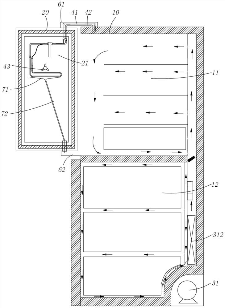
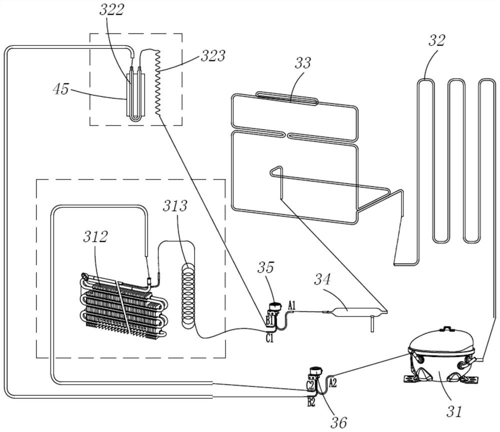
[0031] like Figure 1 to Figure 3 As shown, the refrigerator includes a box body 10, a door body 20 movably conn...


PUM


Abstract

The invention provides a refrigerator control method. The refrigerator control method comprises the following steps that S1, an ice making instruction is received; s2, an electromagnetic valve is controlled to limit flowing of refrigerants in a first refrigerating circuit and to allow flowing of refrigerants in a second refrigerating circuit, the refrigerator operates in an ice-making cold supply mode, the first refrigerating circuit and the second refrigerating circuit are connected to the inlet side of a compressor and the outlet side of a condenser in parallel, and the first refrigerating circuit and the second refrigerating circuit are connected in parallel; the first refrigerating circuit is used for providing cooling capacity for the freezing chamber, and the second refrigerating circuit is used for providing cooling capacity for the ice making chamber; and S3, when it is detected that the temperature in the ice making chamber reaches the preset temperature, the electromagnetic valve is controlled to limit flowing of the refrigerant in the second refrigerating circuit. The refrigerating circuit used for the freezing chamber is cut off in the ice making process, flowing of refrigerants in the refrigerating circuit is stopped, the amount of the refrigerants entering the ice making branch can be reduced, uncontrolled refrigerant distribution caused by refrigerant streaming in the refrigerating circuit switching process in the working process is prevented, and therefore the working reliability of the refrigerating system is improved.

Description

technical field [0001] The invention relates to the technical field of refrigeration, in particular to a control method of a refrigerator with an ice maker. Background technique [0002] In the existing refrigerators capable of making ice, because the ice making needs to be performed below 0 degrees, the ice maker needs to be placed in the freezer, so that the user needs to open the door of the freezer to take out the ice cubes when taking ice. [0003] In order to facilitate the use of users, many refrigerators are provided with an ice maker on the door of the refrigerating compartment of the refrigerator, and a dispenser is arranged outside the refrigerating door, and ice is taken through the dispenser. Generally, the refrigerating evaporator or the freezing evaporator or the cold air in the freezing room is used, that is, the ice making room shares the evaporator with the refrigerating room or the freezing room, and then the air is supplied by the fan to supply the coolin...

Claims


Application Information

Patent Timeline
IPC IPC(8): F25D11/02F25D17/06F25D23/12F25D29/00
CPCF25D11/02F25D17/065F25D23/12F25D29/005
Inventor 李晓峰刘山山刘建如戚斐斐曹东强
Owner QINGDAO HAIER REFRIGERATOR CO LTD
Why Eureka
Try Eureka