Sofa nail frame device with precise positioning structure
A technology of precise positioning and sofa, applied in the direction of manufacturing tools, nailing tools, wood processing appliances, etc., can solve the problem of sofa frame size error, precise positioning of assembly requirements, affecting the quality and aesthetics of the finished sofa, to ensure stable binding. Effect
- Summary
- Abstract
- Description
- Claims
- Application Information
AI Technical Summary
Problems solved by technology
Method used
Image
Examples
Embodiment 1
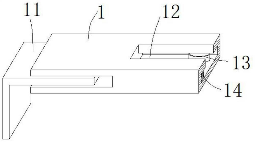
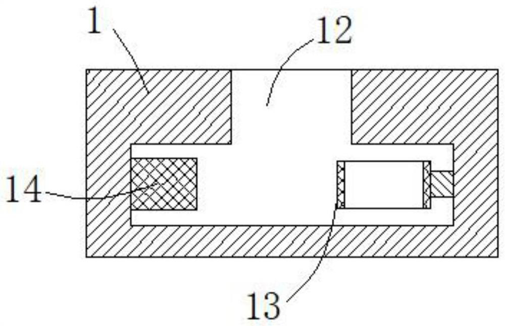
[0032] see figure 1 , image 3 and Figure 4 , the present embodiment provides a sofa nail holder device with a precise positioning structure, including a base plate 1 and a knocking mechanism 2, using the base plate 1 as the supporting base of the knocking mechanism 2, and adjusting the nails from the nail box 22 according to the binding position position to achieve precise positioning of the nails.
[0033]The knocking mechanism 2 includes a horizontal plate 21 and a nail box 22. The upper end of the nail box 22 is provided with a nail releasing slot, and the nails to be used are vertically placed in the nail releasing slot of the nail box 22. The nail outlet that is connected with the nail placement groove is horizontally fed to the air intake to discharge the nails along the interior of the nail placement groove, and the air exhaust nails are led out along the nail outlet in turn for binding the sofa frame.
[0034] One end of the base plate 1 is provided with an invert...
Embodiment 2
[0042] see figure 1 , Figure 5 and Image 6 , made further improvements on the basis of Example 1:
[0043] In order to ensure that the air discharge nails are led out of the nail outlet in an orderly manner, a buffer sleeve 23 is connected to the side wall of the nail box 22 away from the nail outlet, and the buffer sleeve 23 is communicated with the inside of the nail release groove, and the interior of the buffer sleeve 23 is far away from the nail outlet. One end of the nail box 22 is fixedly provided with a guide rod 218 , the outer wall of the guide rod 218 is slidably sleeved with a toggle rod 212 , and the outer wall of the guide rod 218 is sleeved with a guide rod 212 that can push the toggle rod 212 to the side close to the nail box 22 in real time. The first spring 217, the side wall of the lever 212 is fixedly provided with a top rod 214, the top rod 214 slides and extends to the inside of the nail placing slot, and is connected with a top block 215, the elastic...
Embodiment 3
[0047] see figure 1 , Figure 7 and Figure 8 , made further improvements on the basis of Example 2:
[0048] Limiting card slots 213 are provided on both sides of the inner top of the nail-receiving slot of the staple box 22 , and a pressure plate 219 is slidably inserted into the limiting card slot 213 . The interior of the limit card slot 213 is fed horizontally until the notch of the nail placement slot is completely sealed, and the pressure plate 219 is used to prevent the nails from jumping out of the nail placement slot.
[0049] In order to ensure that the air-discharging nails are fed horizontally in the nail-receiving slot, and the phenomenon of shaking during the feeding process will not occur, two pressing rods 220 are slidably inserted at the bottom end of the pressing plate 219. The bottom of the two pressing rods 220 A number of turrets 221 are arranged between the ends, and a connecting rod is fixed between two adjacent turrets 221. The bottom end of each tu...
PUM
 Abstract
Description
Claims
Application Information
 - R&D
- Intellectual Property
- Life Sciences
- Materials
- Tech Scout
- Unparalleled Data Quality
- Higher Quality Content
- 60% Fewer Hallucinations
Browse by: Latest US Patents, China's latest patents, Technical Efficacy Thesaurus, Application Domain, Technology Topic, Popular Technical Reports.
© 2025 PatSnap. All rights reserved.Legal|Privacy policy|Modern Slavery Act Transparency Statement|Sitemap|About US| Contact US: help@patsnap.com


