Node near-field configuration method, control device, controlled target node and near-field node configuration system

A technology for controlling devices and target nodes, which is applied in the direction of electrical components, etc., and can solve problems such as node initialization

Pending Publication Date: 2022-07-01
OPPLE LIGHTING +1
View PDF0 Cites 0 Cited by
  • Summary
  • Abstract
  • Description
  • Claims
  • Application Information

AI Technical Summary

Problems solved by technology

[0003] The purpose of the present invention is to solve the problem in the prior art that all nodes in the network need to be initialized when individual nodes are abnormal, and propose a new near-field node configuration method, a control device, a controlled target node, and Near Field Node Configuration System

Method used


Image

  • Node near-field configuration method, control device, controlled target node and near-field node configuration system
  • Node near-field configuration method, control device, controlled target node and near-field node configuration system
  • Node near-field configuration method, control device, controlled target node and near-field node configuration system

Examples


Embodiment 1

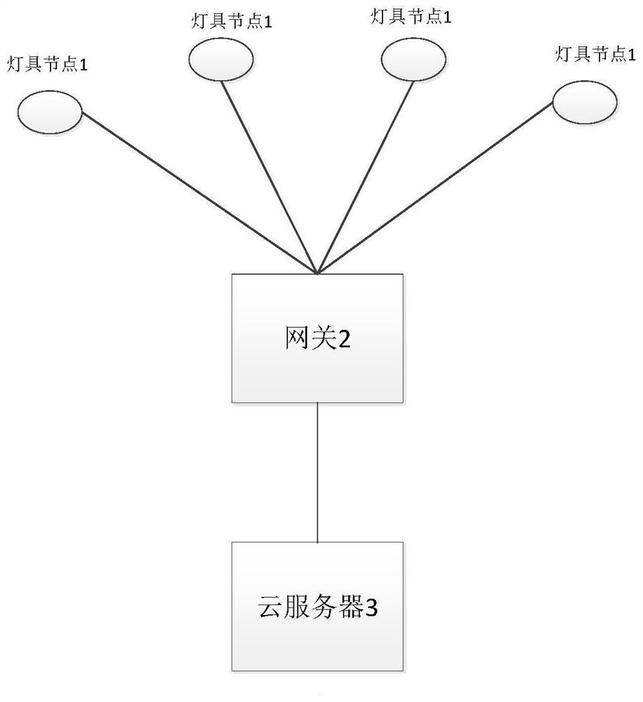
[0029] figure 1 It is a schematic diagram of a preferred lamp node distribution network system according to an embodiment of the present invention.

[0030] like figure 1 As shown, the lighting node distribution network system includes a lighting node 1 , a gateway 2 , and a cloud server 3 . Wherein, during network distribution, a plurality of lamp nodes 1 are securely connected to the gateway 2 by means of key exchange, and the gateway 2 is then electrically connected to the cloud server 3 .

[0031] When multiple lamp nodes 1 have been connected to the gateway 2, but there are individual lamp nodes 1 that cannot be connected to the gateway 2, the individual lamp nodes 1 need to be reconfigured to access the network.

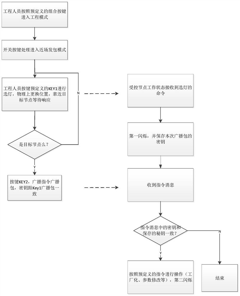
[0032] figure 2 This is a schematic flowchart of a preferred near-field node configuration method according to an embodiment of the present invention.

[0033] like figure 2 As shown, the flow of the near-field node configuration method is as follows:

...


PUM


Abstract

The invention relates to a near-field node configuration method, which is applied to a control device and comprises the following steps: the control device enters a near-field packet sending mode; the control device is close to the controlled target node and broadcasts a lamp selection Beacon data packet, and the lamp selection Beacon data packet comprises a first secret key; after the controlled target node receives a lamp selection Beacon data packet, the control device sends a configuration message to the controlled target node, and the configuration message comprises a second secret key; the first secret key is the same as the second secret key. A key is broadcasted through a physical space lamp end, a correct to-be-selected lamp is confirmed, the key is stored, factory command broadcasting is carried out by using the key, and safety control over a small number of nodes is achieved.

Description

technical field [0001] The invention belongs to the field of node configuration, and in particular relates to a near-field configuration method for individual nodes. Background technique [0002] At present, lighting systems have been combined with smart devices. For example, in commercial lighting systems, users can control the on-off, dimming and color adjustment of multiple lamps through mobile devices or control panels. In the commercial lighting system, the lighting nodes are mainly connected to the network through Bluetooth and other communication methods. When there is an abnormality in a certain node in a certain network and the disconnection is not controlled, the existing technology usually initializes the nodes in the entire network. Thus, all nodes are reconfigured. Obviously, this network distribution method is inefficient and the user's perception is poor. SUMMARY OF THE INVENTION [0003] The purpose of the present invention is to solve the problem in the p...

Claims


Application Information

Patent Timeline
Patent Type & Authority Applications(China)
IPC IPC(8): H05B47/19
CPCH05B47/19
Inventor 夏建明
Owner OPPLE LIGHTING
Why Eureka
Try Eureka