
Coriolis mass flowmeter

A mass flowmeter, Coriolis technology, applied in the direction of direct mass flowmeter, mass flow measurement device, measuring flow/mass flow, etc., can solve the deterioration of flow tube balance and the adverse effects of Coriolis mass flowmeter performance , Without considering the influence of the flow tube, etc., to achieve the effect of high pressure resistance, difficult vibration expansion, and cost reduction

Inactive Publication Date: 2004-04-21
OVAL CORP
View PDF0 Cites 0 Cited by
  • Summary
  • Abstract
  • Description
  • Claims
  • Application Information

AI Technical Summary

Problems solved by technology

However, the existing Coriolis mass flowmeter does not consider the influence of such wiring on the vibration of the flow tube, and the coils of the drive device 15 and a pair of vibration detection sensors 16 and 17 are collectively installed on one flow tube.
The influence of the mass and tension of the wiring is concentrated only on the tube where the coil is installed, so the balance between the two flow tubes deteriorates, which adversely affects the performance of the Coriolis mass flowmeter

Method used


Image

  • Coriolis mass flowmeter
  • Coriolis mass flowmeter
  • Coriolis mass flowmeter

Examples


Embodiment Construction

[0041] Although the present invention can be fully applied to Coriolis mass flowmeters using two parallel flow tubes, the following will take two parallel elbow type, especially gate type Coriolis mass flowmeters as an example. illustrate.

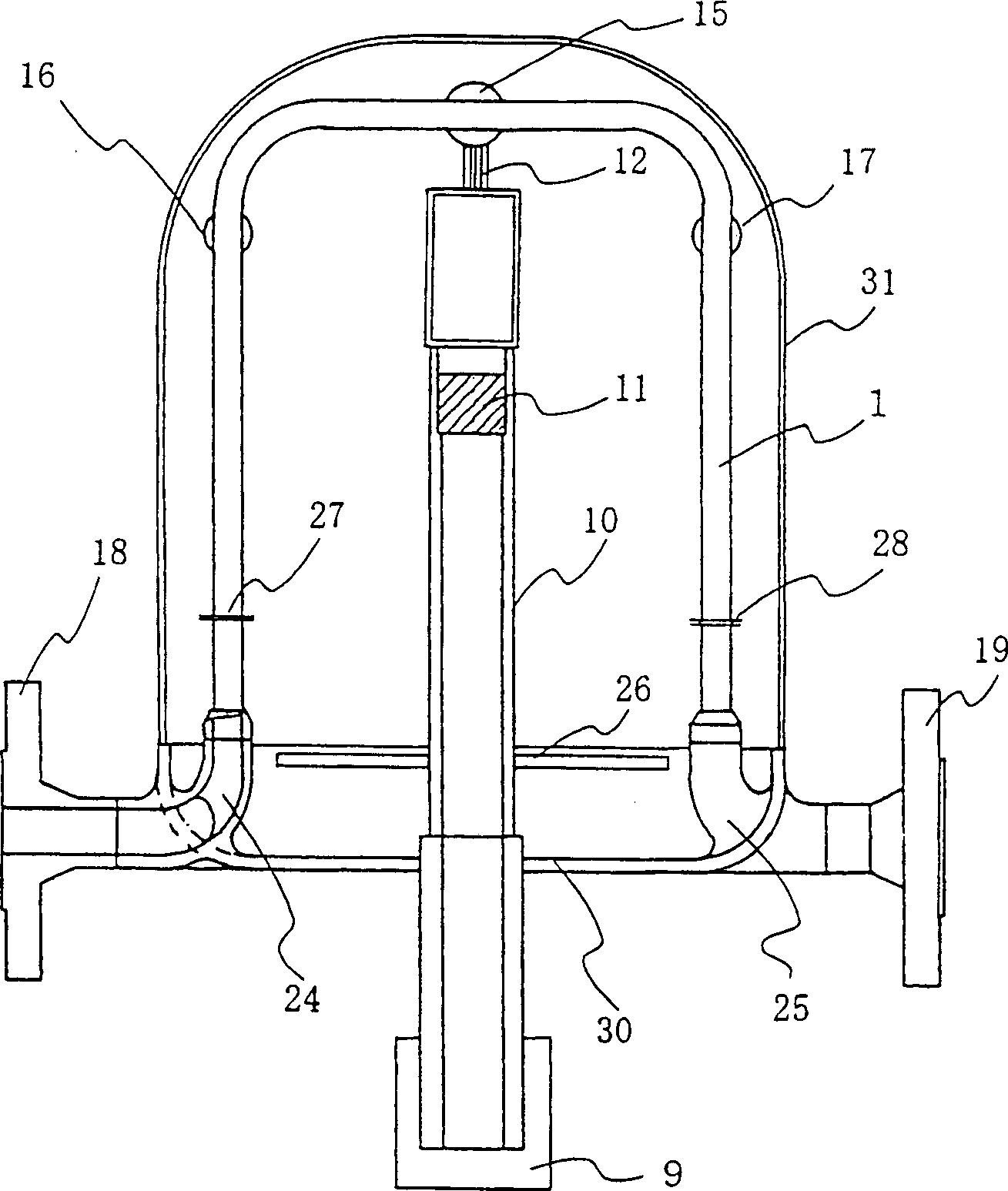
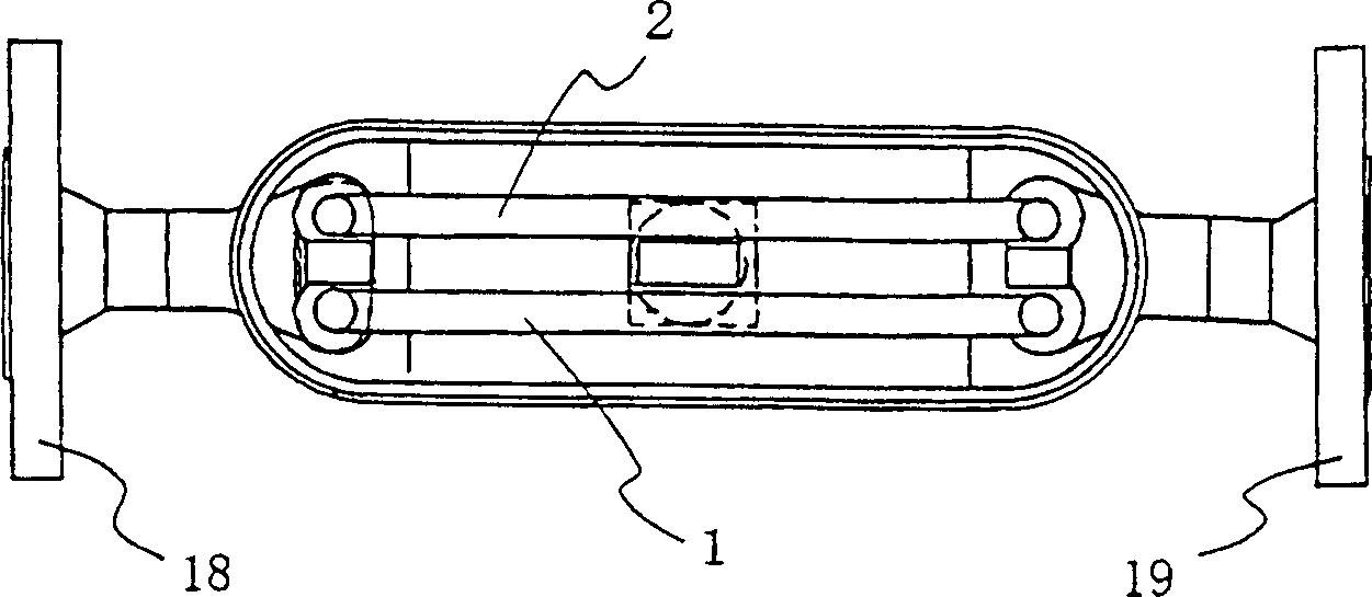
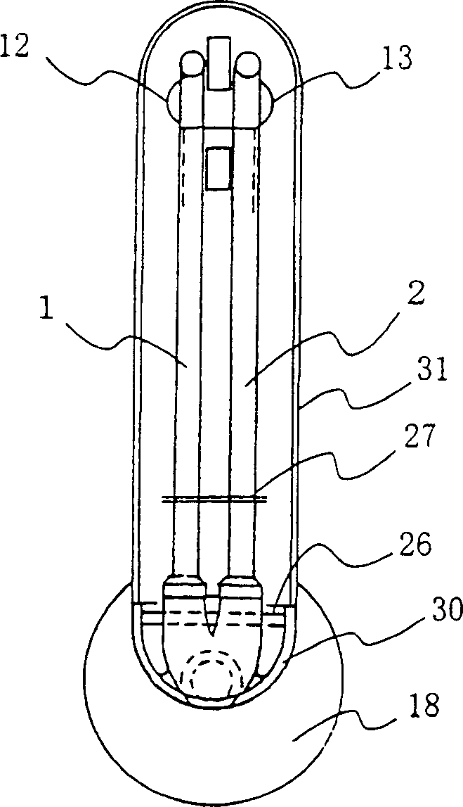
[0042] Figure 1 to Figure 3 It is a diagram showing a first example of a Coriolis mass flowmeter to which the present invention is applied, and imagines a situation in which two elbow-type flow tubes connected in parallel are installed in a vertical plane. figure 1 It is a picture seen from the front. figure 2 is from the top side (from the figure 1 Partial cross-sectional view of a Coriolis mass flowmeter installed in a vertical plane seen from the upper side of image 3 is in the central will figure 1 The cutaway view of the Coriolis mass flow meter shown.

[0043] The flow tubes 1 and 2 of the Coriolis mass flowmeter shown as an example are curved tubes of the same shape bent into a gate shape, and the two end portions of each cu...


PUM


Abstract

The Coriolis mass flow meter of this invention comprises two parallel curved flow tubes 1 and 2, a drive unit 15, and a pair of vibration sensors 16 and 17. An inlet-side manifold 24 dividing the flow of a fluid being measured into the two flow tubes 1 and 2 from the inlet thereof, and an outlet-side manifold 25 joining the fluid flows flowing in the two flow tubes 1 and 2 to discharge from the fluid outlet thereof are mechanically connected to a meter body 30 only at the inlet side of the inlet-side manifold 24 and at the outlet side of the outlet-side manifold 25, respectively. With this arrangement, the effects of vibration transmitted from the meter body 30 and all structures connected thereto can be reduced at the joint parts between the inlet-side and outlet-side manifolds 24 and 25 that serve as vibration fulcrums.

Description

technical field [0001] The invention relates to a Coriolis mass flowmeter, in particular to a Coriolis mass flowmeter using two parallel flow tubes and a configuration method for its coil and magnet. Background technique [0002] A known mass flow meter (Coriolis mass flow meter) is a flow meter that supports one or both ends of a flow tube that flows through the fluid to be measured, and when the flow tube surrounds the support point and along When vibrating in a direction perpendicular to the flow direction of the fluid in the flow tube, the magnitude of the Coriolis force acting on the flow tube (hereinafter referred to as the flow tube to be vibrated) is proportional to the mass flow rate. It is precisely this nature that is used by the plan. The shape of the flow tube as the Coriolis mass flowmeter is roughly divided into a bent tube and a straight tube. [0003] When the straight tube Coriolis mass flowmeter vibrates along the direction perpendicular to the axis of t...

Claims


Application Information

Patent Timeline
Patent Type & Authority Patents(China)
IPC IPC(8): G01F1/84
CPCG01F1/8418G01F1/8427G01F1/8409G01F1/8422G01F1/8477G01F1/84
Inventor 中尾雄一白石泰一二瓶觉小林诚司糸康
Owner OVAL CORP
Learn More