Seat and automobile with same

A technology for seats and automobiles, which is applied in the direction of movable seats, vehicle seats, detachable/non-detachable seats, etc. It can solve the problems of large installation space, complex support device structure, large input power, etc., and achieve power and size small effect

Active Publication Date: 2022-06-28
贵州华阳汽车零部件有限公司
View PDF18 Cites 0 Cited by
  • Summary
  • Abstract
  • Description
  • Claims
  • Application Information

AI Technical Summary

Problems solved by technology

[0002] In order to further improve the utilization rate of the interior space of the vehicle, the current automobile industry is gradually designing the car seat into a form that can be folded and stored. The car folding seat in the prior art usually adopts an electric drive mechanism on one side of the seat cushion, and the electric drive The mechanism cooperates with the reduction box to drive the seat cushion to rotate automatically, so that the seat cushion can be automatically turned into the storage slot; during the rotation process of the electric drive mechanism, before the seat cushion turns to 90°, the electric drive mechanism needs to give the seat cushion a positive traction to drive the seat cushion to rotate, and When the seat cushion is rotated to 90°, it is necessary to give the seat cushion a supporting force in one direction to support the cushion to be slowly folded into the storage slot; but often due to the excessive mass of the seat, the electric drive mechanism requires a large output torque, and then the reduction box and The drive motor is relatively large, and it needs to occupy a large layout space of the car body in the actual matching process with the car body. At the same time, the drive components require greater input power, and the energy consumption of the car is relatively large.
[0003] At the same time, the existing supporting device has a complex structure, low flexibility, large overall volume, and requires a large installation space.

Method used


Image

  • Seat and automobile with same
  • Seat and automobile with same
  • Seat and automobile with same

Examples


Embodiment 1

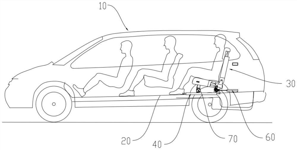
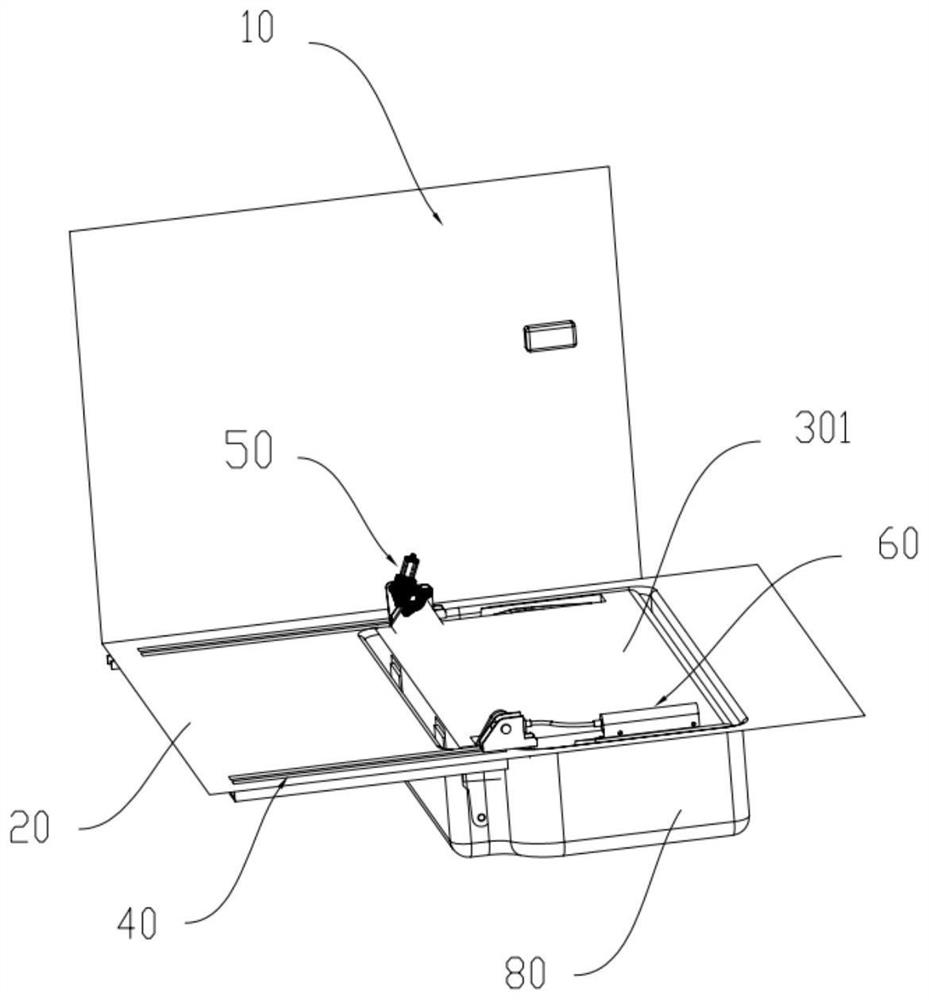
[0088] see figure 2 and Figure 5 , the preferred embodiment of the present invention provides a seat, which is used to be installed on the bottom plate 20 of the automobile 10 to provide a riding function, including a seat body 30, a sliding mechanism 40, an electric drive mechanism 50, an auxiliary device 60 and two The support member 70, the seat body 30 includes a seat cushion 301 and a backrest 302 hinged with the seat cushion 301; the sliding mechanism 40 includes two oppositely arranged sliding rails 401 and a clamping column 402 slidably arranged on the sliding rail 401; the electric drive mechanism 50 is provided with On one of the sliding rails 401, the electric drive mechanism 50 is hinged with the rear end of the seat cushion 301 to drive the seat cushion 301 to turn over; the auxiliary device 60 is arranged on the other sliding rail 401, and the auxiliary device 60 is hinged with the rear end of the seat cushion 301 to It is used to assist the electric drive mec...

Embodiment 2

[0094] see Image 6 , the preferred embodiment of the present invention provides an auxiliary device 60, which is used to rotatably connect the seat and the bottom plate 20, including an actuator 601, a first transmission cable 603 and a power mechanism 602; the actuator 601 includes a first support A frame 6011, a connecting shaft 6012 and a crank 6013, the first support frame 6011 is arranged on the bottom plate 20; one end of the connecting shaft 6012 is rotatably installed on the first support frame 6011, the other end is connected to the seat, and the connecting shaft 6012 rotates with the seat The crank 6013 is sleeved with the connecting shaft 6012, and the crank 6013 rotates with the connecting shaft 6012; one end of the first transmission cable 603 is connected to the crank 6013, and the other end is connected to the power mechanism 602; The first torque, and the power mechanism 602 pulls the first transmission cable 603, so that the crank 6013 receives a second torqu...

Embodiment 3

[0113] see Figure 8 Compared with the embodiment, this embodiment adopts a different power mechanism 602. The power mechanism 602 of this embodiment includes a casing 6021, a first support shaft 6024, a first torsion spring 6025 and a support ring 6026, and the first support shaft 6024 is provided with The support ring 6026 is arranged on the housing 6021, and the support ring 6026 is coaxial with the first support shaft 6024, and the support ring 6026 is provided with a lap groove 60261; the first torsion spring 6025 has a first support arm 60251 and The second support arm 60252, the first torsion spring 6025 are sleeved on the first support shaft 6024, and the first support arm 60251 is inserted into the lap groove 60261; the second support arm 60252 is connected with the other end of the first transmission cable 603 .

[0114] Specifically, the first support arm 60251 is locked in the lap groove 60261 and cannot move, so that the first torsion spring 6025 cannot rotate; w...


PUM


Abstract

The invention relates to the technical field of automobile seats, and discloses a seat and an automobile with the seat, the seat comprises a seat body, a clamping column, an electric driving mechanism, an auxiliary device and two supporting parts, the seat body comprises a cushion and a backrest hinged to the cushion; the clamping column is arranged on the vehicle bottom plate; the electric driving mechanism is arranged on a vehicle bottom plate and hinged to the rear end of the cushion so as to be used for driving the cushion to turn over; the auxiliary device is arranged on a vehicle bottom plate, is hinged to the rear end of the cushion and is used for assisting the electric driving mechanism to drive the cushion to turn over; each supporting component comprises a first end and a second end, the first end is hinged to the front end of the cushion, and the second end is provided with a lock hook matched with the clamping column for locking; in the overturning process of the seat, torque compensation can be carried out on the electric driving mechanism, and the output torque of the electric driving mechanism is reduced.

Description

technical field [0001] The present invention relates to the technical field of automobile seats, in particular to a seat and an automobile having the same. Background technique [0002] In order to further improve the utilization rate of the interior space of the vehicle, the current automobile industry is gradually designing the car seat into a form that can be folded and stored. The car folding seat in the prior art usually adopts an electric drive mechanism on one side of the seat cushion. The mechanism cooperates with the reduction box to drive the seat cushion to rotate automatically, so that the seat cushion can be automatically transferred to the storage slot; during the rotation of the electric drive mechanism, before the seat cushion is rotated to 90°, the electric drive mechanism needs to give the seat cushion a positive traction to drive the seat cushion to rotate, while When the seat cushion is rotated to 90°, it is necessary to give the seat cushion a support fo...

Claims


Application Information

Patent Timeline
Patent Type & Authority Applications(China)
IPC IPC(8): B60N2/02B60N2/30
CPCB60N2/3011B60N2/02258B60N2/02253B60N2/02246
Inventor 王俊李航宇何正远蔡建波郑迎
Owner 贵州华阳汽车零部件有限公司
Why Eureka
Try Eureka