
Gantry machining center

A machining center and gantry technology, applied in metal processing equipment, metal processing machinery parts, manufacturing tools, etc., can solve the problem of long debugging time for debugging the fourth axis, affecting the reliable movement of the machine head module, affecting the processing accuracy of products, etc. problems, to achieve the effects of shortening assembly time, facilitating waste disposal work, and accurate parallelism

Active Publication Date: 2022-06-28
长浦智能装备(广东)有限公司
View PDF5 Cites 0 Cited by
  • Summary
  • Abstract
  • Description
  • Claims
  • Application Information

AI Technical Summary

Problems solved by technology

[0003] For the gantry machining center based on this structural arrangement, in the process of using the gantry machining center, if it is necessary to add a fourth axis; based on the structure of the T-slot platform, the axial parallelism of the fourth axis is corrected when it is installed. It is very difficult, and it will take a long time to debug the fourth axis; if there is a deviation in the parallelism of the fourth axis, it will affect the processing accuracy of subsequent products
If the fourth axis is installed on the T-slot platform to process the product, the waste generated by the product will fall directly on the T-slot platform and cause accumulation, requiring workers to clean it; and, the waste accumulated on the T-slot platform Chips often fall on the guide rails, which affects the reliable movement of the head module

Method used


Image

  • Gantry machining center
  • Gantry machining center
  • Gantry machining center

Examples


Embodiment Construction

[0035] The technical solutions in the embodiments of the present invention will be clearly and completely described below with reference to the accompanying drawings in the embodiments of the present invention. Obviously, the described embodiments are only a part of the embodiments of the present invention, but not all of the embodiments. Based on the embodiments of the present invention, all other embodiments obtained by those of ordinary skill in the art without creative efforts shall fall within the protection scope of the present invention.

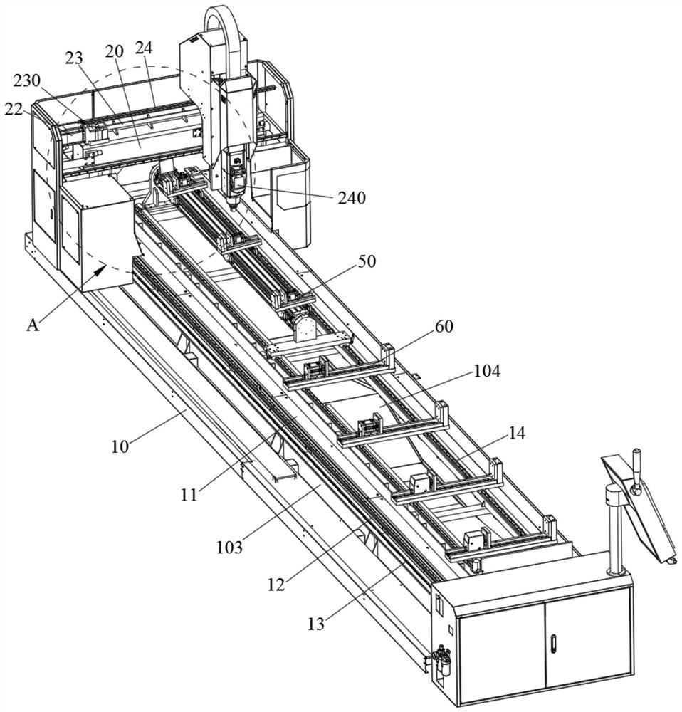
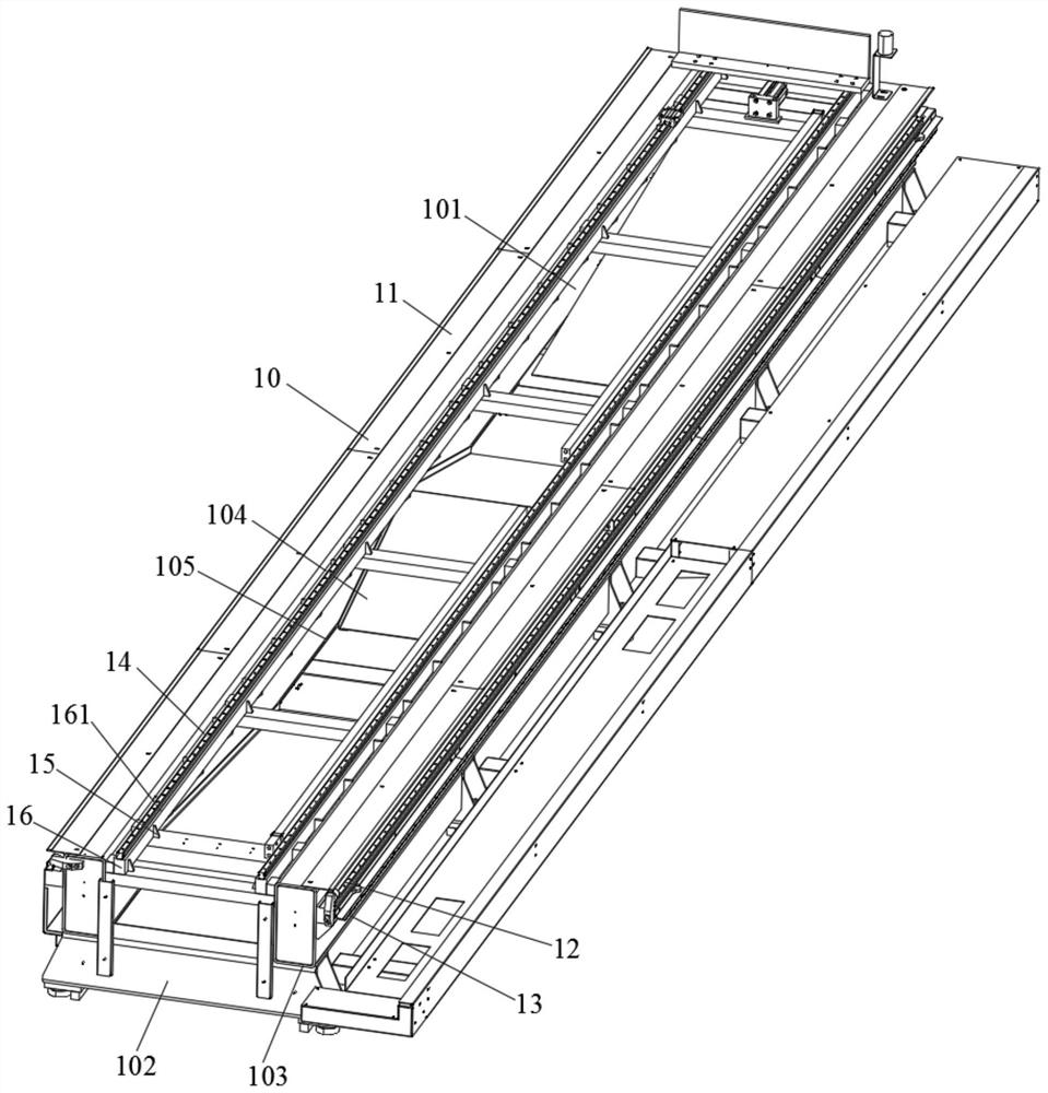
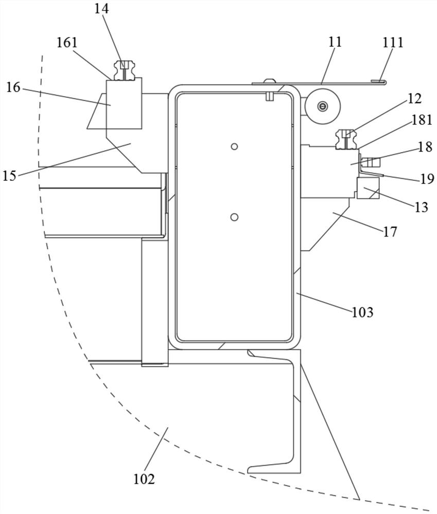
[0036] like Figure 1-Figure 6 The shown gantry machining center includes a machine body 10 on which a gantry frame 20 is movably arranged, and a deceleration motor 1 30 is provided at the bottom of the gantry frame 20 through a fixing plate 1 31, and the gantry frame 20 A fourth axis module 40 is provided thereon, a first clamp assembly 50 is movably disposed on the fourth axis module 40, and a second clamp assembly 60 is movably dis...


PUM


Abstract

The invention discloses a gantry machining center, and relates to the technical field of mechanical equipment, the gantry machining center comprises a machine tool body, a portal frame is movably arranged on the machine tool body, a first gear motor is arranged at the bottom of the portal frame through a first fixing plate, a fourth shaft module is arranged on the portal frame, and a first clamp assembly is movably arranged on the fourth shaft module; a second clamp assembly is movably arranged on the machine tool body. By arranging the second guide rail and the fourth shaft module, the effect of improving the precision of the fourth shaft module is achieved, the second guide rail is arranged on the machine tool body, a fixed seat of the fourth shaft module is fixed to the machine tool body, a second sliding block at the bottom of a movable seat slides on the second guide rail, and the parallelism of the second guide rail serves as the assembling reference of the fourth shaft module; the parallel mechanism has more accurate parallelism, does not need an operator to debug the parallelism, is convenient to install, shortens the time consumed by assembly, and saves time and labor.

Description

technical field [0001] The invention relates to the technical field of mechanical equipment, in particular to a gantry machining center. Background technique [0002] With the development of my country's manufacturing industry, the application of CNC machine tools is becoming more and more extensive, and the gantry-type machine tools are also more and more widely used. The worktable of the traditional CNC gantry machining center and the guide rails for the movement of the head module are installed on the machine body. Usually the guide rails are installed on the left and right sides of the worktable; for the worktable, T-slots are generally used. platform. [0003] For the gantry machining center based on this structural arrangement, in the process of using the gantry machining center, if the fourth axis needs to be added; based on the structure of the T-slot platform, the parallelism of the axial direction of the fourth axis is aligned when the fourth axis is installed. I...

Claims


Application Information

Patent Timeline
Patent Type & Authority Applications(China)
IPC IPC(8): B23Q1/01B23Q3/08B23Q11/00B23Q11/08
CPCB23Q1/015B23Q1/017B23Q3/08B23Q11/08B23Q11/0042Y02P70/10
Inventor 苏剑超谭礼财林子谋
Owner 长浦智能装备(广东)有限公司
Learn More