


Quick Research
Generate reliable direction feasibility study reports for your R&D in just a few steps.

Technical Q&A
Discover and master advanced knowledge NOW. Basics, ideas, possibilities, all at once.

Find Solutions
As an expert in R&D theories, this can generate solutions to your technical problems instantly.

Evaluate Feasibility
Analyze your overall solution with one click, know your potential R&D risks in advance.

Monitor Landscape
Get weekly tech updates, stay abreast of the latest tech innovations and key insights.
Three-position isolation grounding switch and isolation static contact
A static contact and contact technology, which is applied in grounding switches, air switch parts, contact surface shape/structure, etc., can solve the problem of not easy to replace the strap contact fingers, reduce risks, and facilitate disassembly. the effect of
- Summary
- Abstract
- Description
- Claims
- Application Information
AI Technical Summary
Problems solved by technology
Method used
Image

Examples
Embodiment 1
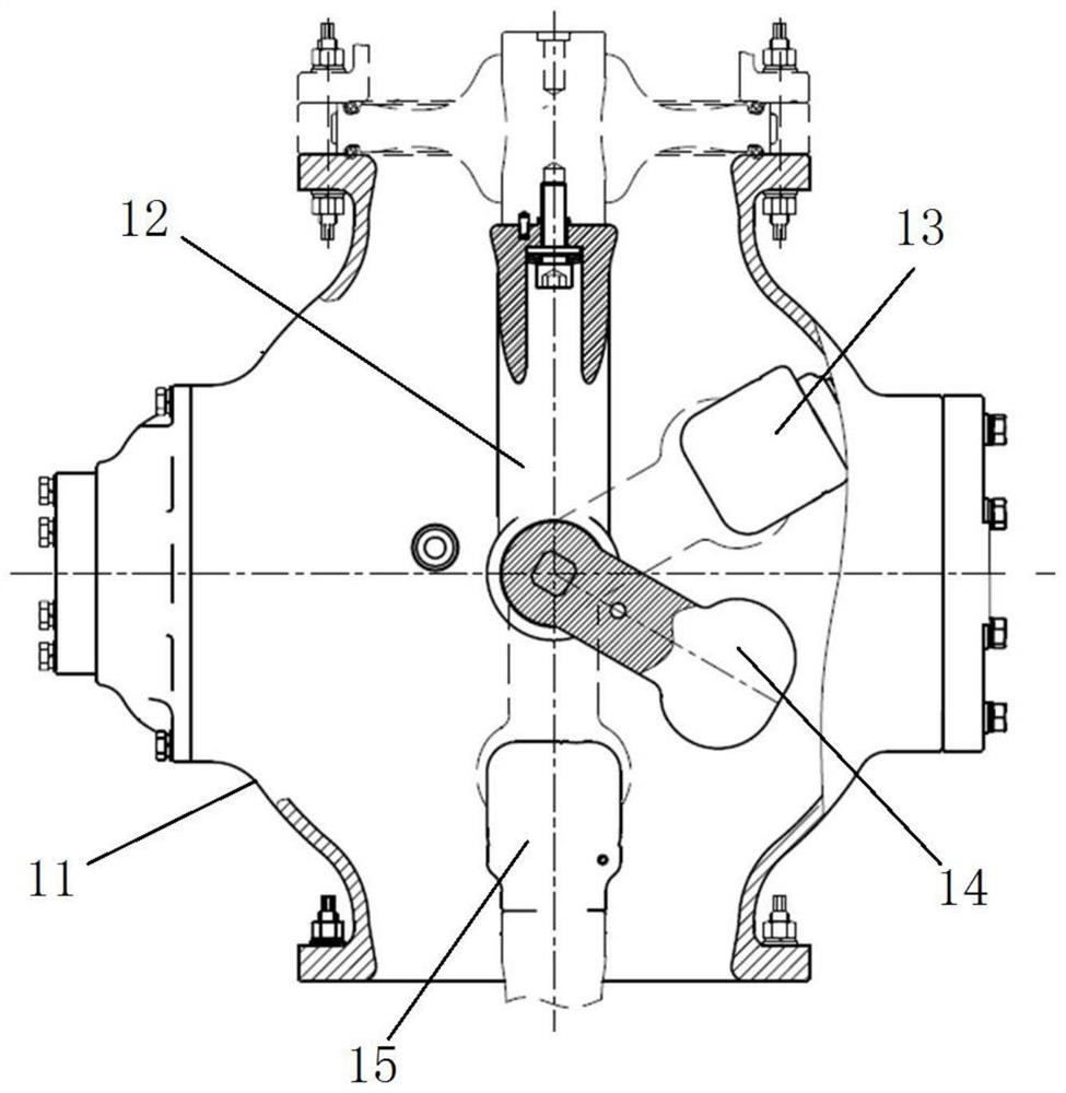
[0054] like figure 1 As shown, the three-position isolating grounding switch includes a housing 11, and a movable support 12 extending in the vertical direction is arranged in the housing 11. The lower end of the movable support 12 is connected with a movable contact 14, and the upper end of the movable support 12 is connected Fixed on the top of the housing 11 . The housing is also provided with an isolation static contact 15 and a grounding static contact 13 .
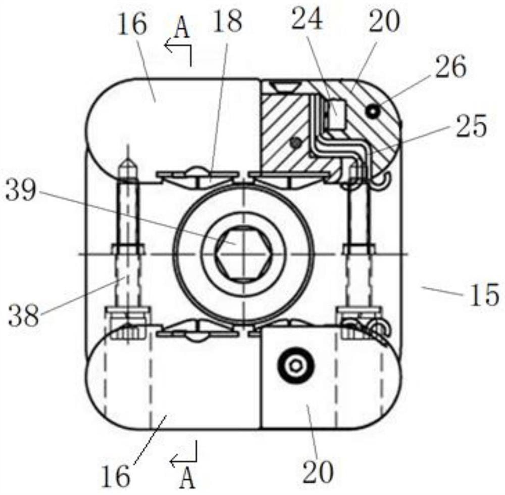
[0055] like image 3 As shown, the isolated static contact 15 is fixed to other conductors in the housing 11 by the fifth screw 39 .
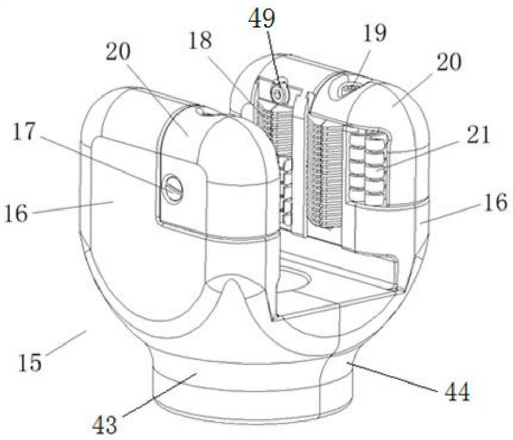
[0056] The direction in which the movable contact 14 is inserted into the isolation static contact 15 is defined as the left-right direction. like figure 2 , Figure 4 and Image 6 As shown, the isolation static contact 15 includes a front contact unit 43 and a rear contact unit 44, the front contact unit 43 includes a front vertical seat, and the rear contact unit 44 includes ...
Embodiment 2
[0074]The difference between this embodiment and Embodiment 1 is that, in Embodiment 1, the lower part of the groove bottom of the contact finger installation groove 46 is fitted with a limit pin 48 by interference, and the limit pin 48 constitutes a lower limit piece. In this embodiment, the lower part of the groove bottom of the contact finger installation groove is threadedly connected with a limit bolt, and the limit bolt constitutes a lower limit member. In other embodiments, based on the case where the lower limiting member is a limiting bolt, the upper limiting member on the left side may be designed as a limiting pin.
Embodiment 3
[0076] The difference between this embodiment and Embodiment 1 is that, in Embodiment 1, the lower part of the groove bottom of the contact finger installation groove 46 is fitted with a limit pin 48 by interference, and the limit pin 48 constitutes a lower limit piece. In this embodiment, the lower part of the groove bottom of the contact finger installation groove is protruded with a limit protrusion, and the limit protrusion constitutes a lower limit member.
PUM
 Abstract
Description
Claims
Application Information
 - R&D Engineer
- R&D Manager
- IP Professional
- Industry Leading Data Capabilities
- Powerful AI technology
- Patent DNA Extraction
Browse by: Latest US Patents, China's latest patents, Technical Efficacy Thesaurus, Application Domain, Technology Topic, Popular Technical Reports.
© 2024 PatSnap. All rights reserved.Legal|Privacy policy|Modern Slavery Act Transparency Statement|Sitemap|About US| Contact US: help@patsnap.com