
Thin steel strip telescopic structure and selfie stick with thin steel strip telescopic structure

A technology of telescopic structure and telescopic rod, which is applied to the structure of telephones, etc., can solve problems such as equipment failure, damage to spiral wires, and limited application scenarios, and achieve the effect of low cost and simple structure

Active Publication Date: 2022-06-17
江苏大勇机器人科技有限公司
View PDF5 Cites 0 Cited by
  • Summary
  • Abstract
  • Description
  • Claims
  • Application Information

AI Technical Summary

Problems solved by technology

[0002]Existing telescopic rods are generally composed of a group of sleeves with different diameters that are sheathed together, and their length can be manually extended or shortened, but not automatically Elongated or shortened, causing inconvenience to use
Some telescopic rods can be automatically extended and retracted. Generally, a built-in motor drives a multi-section threaded sleeve to realize the longitudinal telescopic movement of the telescopic rod. their application scenarios
[0003] In addition, the existing telescopic rods use spiral wires for conductive connection to transmit power to the electrical equipment installed on the telescopic rods. The spiral wires first take up space It is very large, which will cause the volume of the telescopic rod to become larger and not compact

Method used


Image

  • Thin steel strip telescopic structure and selfie stick with thin steel strip telescopic structure
  • Thin steel strip telescopic structure and selfie stick with thin steel strip telescopic structure
  • Thin steel strip telescopic structure and selfie stick with thin steel strip telescopic structure

Examples


Example Embodiment

[0095]实施例1

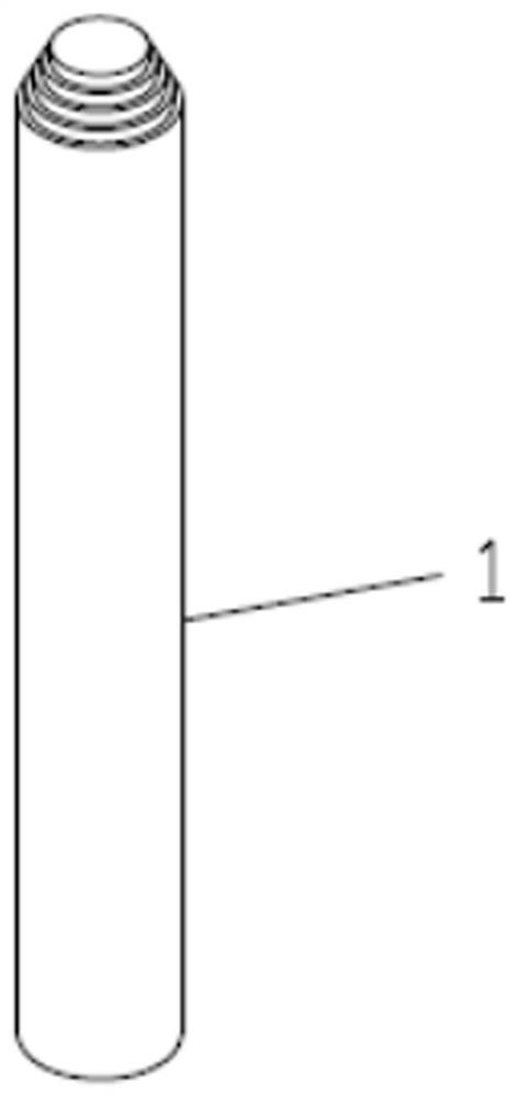
[0096]参看图1-图12,具有薄钢带伸缩结构自拍杆,包括手机支架2和套筒式伸缩杆1,包括手机支架2,所述套筒式伸缩杆1的上端连接有手机支架2,所述伸缩结构的的外部设有手柄套4。

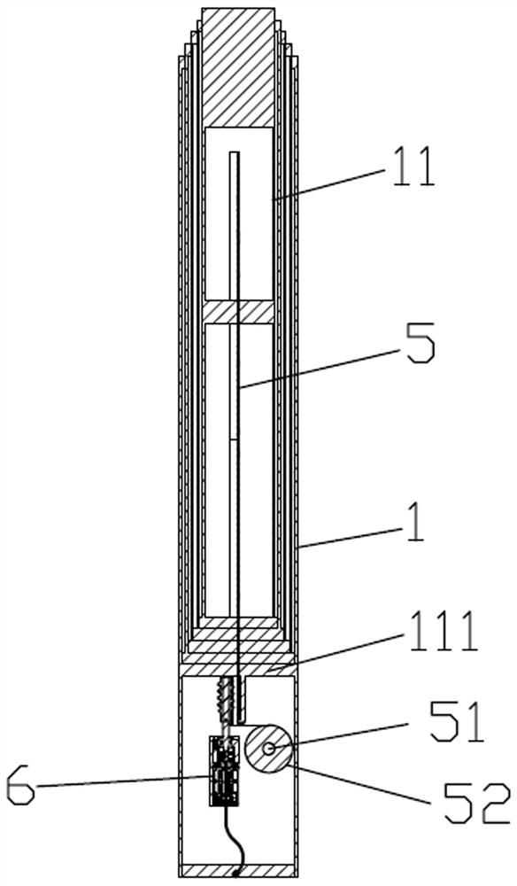
[0097]所述套筒式伸缩杆1由n节直径不等的套管11穿套在一起组成,n节所述套管11由下而上依次穿套组合,最下端的一节所述套管11到最上端的一节所述套管11依次计为第1节套管,第2节套管,第3节套管……第n节套管。在本实施例中,套筒式伸缩杆1由五节相互穿套设置在一起的有效长度为0.6米的套管11组成,上一节套管11的外径均略小于其相邻连接的下一节套管11的内径。因此在本实施例中,由下而上依次穿套组合第1节套管,第2节套管,第3节套管,第4节套管11和第5节套管11,形成本实施例的套筒式伸缩杆1。

[0098]作为对本实施例的进一步说明,所述伸缩结构还包括弹性薄钢带5,所述弹性薄钢带5设置于所述套筒式伸缩杆1内,且弹性薄钢带5的一端固定设置于最上端的所述第n节套管内,所述弹性薄钢带5的另一端在最下端的所述第1节套管的下方卷绕收纳。具体地,所述弹性薄钢带5的下端可固定在绕卷架51,由此实现弹性薄钢带5的展开和收纳。

[0099]在上述弹性薄钢带5的下端固定方式中,也可以将所述弹性薄钢带5的下端制作为一段自卷绕呈涡卷状的薄钢带,这段自卷绕呈涡卷状的薄钢带材定型为其外径在无外力状态下小于实际使用中的最小外径的弹性卷曲层52,弹性卷曲层52始终具有对薄钢带材内层弹性卷曲层52施加径向卷绕压力,即具有自卷曲的弹性势能。这样弹性薄钢带5的下端可延伸至驱动装置的下面的大一些的空间自卷绕,以方便伸缩杆的进一步小型化。

[0100]作为对本实施例的进一步说明,所述弹性薄钢带5由优质弹簧钢制作而成。在本实施例中,弹性薄钢带5的长度设置为1米,厚0.2毫米。为了适应不同长度的伸缩需要,可对弹性薄钢带5的长度做适应性调整。在本实施例中,所述弹性薄钢带横截面53所跨过的弧度为45°,弹性薄钢带横截面53内壁半径5毫米。

[0101]作为对本实施例的进一步说明,所述伸缩结构还包括驱动装置6,所述驱动装置6的输出端与弹性薄钢带5相啮合。

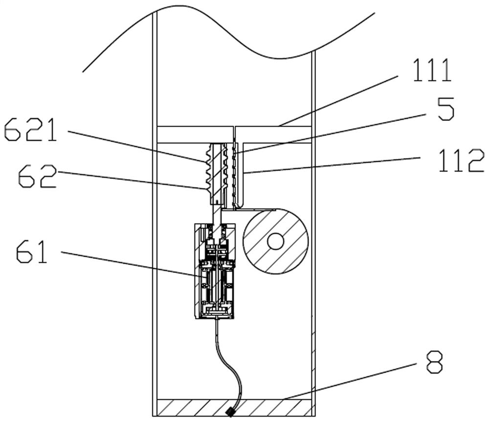
[0102]作为对本实施例的进一步说明,所述驱动装置6包括由驱动电机61和驱动件62组成的传动系统,所述驱动件62为驱动蜗杆621或者驱动齿轮,所述驱动电机61的输出端...

Example Embodiment

[0111]实施例2

[0112]参看图13,与实施例1不同的点在于:本实施例的最下端的第1节套管的管壁内侧下端设有封板111,所述封板111的中部设有形状与所述弹性薄钢带横截面53相吻合的弧形孔114。当所述套筒式伸缩杆1处于收缩状态时,所有套管11的封板111上的弧形孔114的轮廓重合。

[0113]当最下端的第1节套管的管壁内侧下端设有封板111时,所述封板111的的底部连接有伸缩杆底座3,所述伸缩杆底座3的底部设有封堵板8,由此在所述封板111和封堵板8之间形成有安装所述驱动装置6的空间。

[0114]具体地,在本实施例中,伸缩杆底座3的设计大小由安装驱动装置6的空间大小决定,其中安装驱动装置6的空间越大。在本实施例中,所述封板111的位置位于最下端的第1节套管的管壁下端,并在伸缩杆底座3的底部设有封堵板8,让所述封板111和封堵板8之间形成有安装驱动装置6的空间。

[0115]所述伸缩杆底座3的外部设有手柄套4。在实施例1中由于不设置伸缩杆底座3,手柄套4可直接设置于最下端的第1节套管的外壁上。

Example Embodiment

[0116]实施例3

[0117]参看图14-17,在实施例1的基础上,当伸缩结构处于无电时或者驱动装置6出现故障时,仍然可以正常使用,本发明设置了离合装置7,可以很方便地实现自拍杆在手动伸缩模式和自动伸缩模式之间转换,当自拍杆处于自动模式无电时或者驱动装置6出现故障时,可以一键手动转换为手动模式,不影响用户正常使用。

[0118]作为对本实施例的进一步说明,所述离合装置7用于使驱动件62的齿与弹性薄钢带5上的孔槽54处于啮合与分离两种状态。具体地,离合装置7可以有三种设置方式,具体为第一离合装置71、第二离合装置72和第三离合装置73。下面针对三种离合装置7做具体的说明。

[0119]作为对本实施例的进一步说明,当所述离合装置7为第一离合装置71时,所述第一离合装置71包括压簧711、滑块712和滑座713,所述滑座713设置于所述第1节套管的内侧壁上或者伸缩杆底座3的内侧壁上,所述滑座713内设有滑块712,所述滑块712与滑座713之间放置有压簧711,所述滑块712连接有电机支架63或者所述滑块712和电机支架63一体成型设置。

[0120]作为对本实施例的进一步说明,所述第一离合装置71还包括第一按钮714和第一自锁式推杆开关715,所述第一按钮714设置于所述伸缩结构的侧面,所述第一自锁式推杆开关的支座716固定在正对所述传动系统的所述第1节套管的内侧壁上或者伸缩杆底座3的内侧壁上;所述第一自锁式推杆开关715的一端设有推杆717,所述推杆717与所述驱动电机61的侧壁相抵,通过在所述第1节套管的内侧壁上或者伸缩杆底座3的内侧壁开设有第一安装孔718,所述第一自锁式推杆开关715的另一端通过第一安装孔718安装有所述第一按钮714。

[0121]作为对本实施例的进一步说明,当所述滑块712和电机支架63一体成型设置时,第一离合装置71由一个自锁式推杆开关构成,第一自锁式推杆开关715的推杆717的一端与蜗杆传动系统的电机侧壁相抵,第一自锁式推杆开关715的操纵端贯穿最外面一节套管11的内侧壁上的开孔露出套管11外且端部呈第一按钮714形状。电机支架63的下端部左侧做成滑块712形状,滑块712与滑座713可滑移地配合,滑块712与滑座713之间放置有压簧711,按动该第一按钮714可以使驱动件62上的齿与弹性薄钢带5上的孔槽54处于啮合与分离两种状态。具体地...


PUM


Abstract

The invention relates to the field of telescopic rods, and particularly discloses a thin steel strip telescopic structure and a selfie stick with the thin steel strip telescopic structure, the thin steel strip telescopic structure comprises a sleeve type telescopic rod, the sleeve type telescopic rod is formed by sleeving n sections of sleeves with different diameters, the selfie stick further comprises an elastic thin steel strip, and the elastic thin steel strip is arranged in the sleeve type telescopic rod; and one end of the elastic thin steel belt is fixedly arranged in the nth section of sleeve at the uppermost end, and the other end of the elastic thin steel belt is wound and stored below the first section of sleeve at the lowermost end. The selfie stick further comprises a driving device, and the output end of the driving device is meshed with the elastic thin steel belt. The selfie stick can control the telescopic speed and has the advantages of being simple in structure, low in cost, long in service life, easy to install and maintain and the like. When no power exists or the driving device breaks down, the rod body can be stretched or shortened manually, normal use of a user is not affected, and the dual-purpose selfie rod compatible with automatic stretching and manual stretching is provided.

Description

technical field [0001] The present invention relates to the field of telescopic poles, and in particular to a thin steel strip telescopic structure and a selfie stick having a thin steel strap telescopic structure. Background technique [0002] Existing telescopic rods are generally composed of a group of casing pipes with different diameters that are sheathed together, and their length can be manually extended or shortened, but cannot be automatically extended or shortened, which brings inconvenience to use. Some telescopic rods can be automatically extended and retracted. Generally, the built-in motor drives a multi-section threaded sleeve to realize the longitudinal telescopic movement of the telescopic rod. their application scenarios. [0003] In addition, the existing telescopic rods use spiral wires for conductive connection to transmit power to the electrical equipment installed on the telescopic rods. The spiral wires first take up a lot of space, which will cause ...

Claims


Application Information

Patent Timeline
IPC IPC(8): H04M1/04
CPCH04M1/04
Inventor 李志明
Owner 江苏大勇机器人科技有限公司
Learn More