Automobile interior lamp panel cutting device and using method thereof
A technology for automotive interiors and light panels, applied in metal processing, etc., to achieve the effects of easy collection, reduced use quantity, and simple structure
Active Publication Date: 2022-06-10
江苏必拓汽车部件有限公司
View PDF6 Cites 4 Cited by
- Summary
- Abstract
- Description
- Claims
- Application Information
AI Technical Summary
Problems solved by technology
[0003] During the use of the existing interior lamp cutting device, it is not convenient to compress and fix the lamp panel material, and manual compression is required, which is low in safety. It is not convenient to batch cut the lamp panels of the same length. During the cutting process, the operator generally judges the cutting position. In addition, it is not convenient to collect the cutting debris well during cutting. The use effect is not good, and the automatic cutting effect is not good, so we propose a car interior lamp panel cutting device and its use method
Method used
View moreImage
Smart ImageViewing Examples
Examples
Embodiment Construction
Login to View More PUM
 Abstract
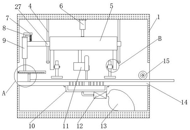
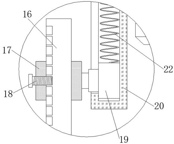
The invention discloses an automotive trim lamp panel cutting device and a using method thereof.The automotive trim lamp panel cutting device comprises a cutting machine body, a feeding port is formed in one side wall of the cutting machine body, an observation window is formed in the front surface of the cutting machine body, a telescopic air cylinder is fixed to the inner side of the cutting machine body, and a first mounting block is arranged at the lower end of the telescopic air cylinder; a second guide block is fixed to the side wall of the first mounting block, a guide groove is formed in the inner side of the second guide block, and a guide rod is fixed to the inner side of the cutting machine body. According to the lamp panel cutting device, a pressing sliding block, a fixing block, a second spring, a pressing plate, an adjusting block and a limiting screw rod are arranged, a lamp panel is prevented from moving in the cutting process, the device can adjust the position of the adjusting block, and the pressing effect is easily adjusted according to the actual thickness of the panel; and movement of the lamp panel materials can be conveniently limited, and then the lamp panel materials of different lengths can be conveniently cut.
Description
technical field [0001] The invention belongs to the technical field of automotive interior lamp cutting, and in particular relates to an automotive interior lamp panel cutting device and a use method thereof. Background technique [0002] Automobile has the following definition: powered by non-rail vehicles with 4 or more wheels, mainly used for: carrying people and (or) goods; traction vehicles carrying people and (or) goods; special purpose, During the processing of automotive interior lamps, in order to facilitate the cutting of the lamp panels, it is generally carried out by a simple cutting machine. [0003] During the use of the existing interior lamp cutting device, it is inconvenient to compress and fix the lamp panel material, which requires manual compression, which has low safety and is not convenient for batch cutting of lamp panels of the same length. During the cutting process, the operator generally judges the cutting position. In addition, it is not convenie...
Claims
Login to View More Application Information
Patent Timeline
 Patent Type & Authority Applications(China)
IPC IPC(8): B26D7/01B26D7/06B26D7/18
CPCB26D7/015
Inventor 杨勇凌武刚
Owner 江苏必拓汽车部件有限公司
Features
- R&D
- Intellectual Property
- Life Sciences
- Materials
- Tech Scout
- Unparalleled Data Quality
- Higher Quality Content
- 60% Fewer Hallucinations
Learn More Browse by: Latest US Patents, China's latest patents, Technical Efficacy Thesaurus, Application Domain, Technology Topic, Popular Technical Reports.
© 2025 PatSnap. All rights reserved.Legal|Privacy policy|Modern Slavery Act Transparency Statement|Sitemap|About US| Contact US: help@patsnap.com


