Radiating unit

A radiation unit and radiator technology, which is applied in the field of radiation units, can solve problems such as narrow standing wave bandwidth of radiation units, and achieve the effect of realizing broadband and reducing size

Active Publication Date: 2022-06-07
HUNAN MAXWELL ELECTRONICS TECH
View PDF8 Cites 1 Cited by
  • Summary
  • Abstract
  • Description
  • Claims
  • Application Information

AI Technical Summary

Problems solved by technology

Under the small size and low profile, the standing wave bandwidth of the radiating unit is designed by conventional means

Method used


Image

  • Radiating unit
  • Radiating unit
  • Radiating unit

Examples


Embodiment 1

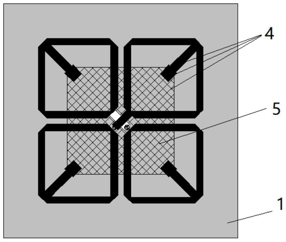
[0025] refer to Figure 1-4 , this embodiment provides a radiation unit, which includes:

[0026] Radiator 2, dielectric substrate 1, feed structure 3, first reflector 5, air resonant cavity, second reflector 6, LC extension circuit 4;

[0027] The first reflector 5 is located on the bottom layer of the dielectric substrate 1 .

[0028] The dielectric substrate 1 of this embodiment has two sides, which are divided into a top layer and a bottom layer, wherein the top layer and the bottom layer are used to describe the circuits respectively arranged on the dielectric substrate, such as the first reflector, which does not necessarily specify which side must be the top layer.

[0029] The LC extension circuit is composed of a first open line printed on the inner or outer frame of the radiator 2 and a second open line coupled with the first reflector 5; the first open line of the inner frame of the radiator is connected to the first open line The coupling of the reflector acts as...


PUM


Abstract

The invention provides a radiation unit. The radiation unit comprises a radiator, a dielectric substrate, a feed structure, a first reflector, an air resonant cavity, a second reflector and an LC frequency-broadening circuit, wherein the LC frequency-broadening circuit is composed of a first open-circuit line printed on an inner frame or an outer frame of the radiator and a second open-circuit line coupled with the first reflector; the first open-circuit line of the inner frame or the outer frame of the radiator plays a role of an inductor L, the second open-circuit line is coupled with the first reflector to play a role of a capacitor C, and the first open-circuit line is thinner than the second open-circuit line. According to the invention, the thin open line and the wide body line are printed on the inner frame or the outer frame of the radiation unit, and the printed thin open line and the wide body line are coupled with the first reflector to form the LC frequency-broadening circuit, so that the size of the radiation unit can be greatly reduced, and the broadband of the radiation unit can be realized.

Description

technical field [0001] The present invention relates to the field of radio frequency technology, and in particular, to a radiation unit. Background technique [0002] Modern phased array antennas require a large scanning angle and a windward area as small as possible, while a phased array antenna that meets ±60° electrical scanning angle requires that the area of ​​a single antenna unit is less than 0.25λ^2, and the size of the antenna unit is much smaller than half a wavelength. Under the small size and low profile, the standing wave bandwidth of the radiation unit is designed by conventional means. [0003] The background description provided herein is for the purpose of generally presenting the context of the disclosure. Unless otherwise indicated herein, the material described in this section is not prior art to the claims in this application and is not admitted to be prior art by inclusion in this section. SUMMARY OF THE INVENTION [0004] In view of the above techn...

Claims


Application Information

Patent Timeline
Patent Type & Authority Applications(China)
IPC IPC(8): H01Q1/38H01Q1/50H01Q3/34H01Q15/14H01Q19/10
CPCH01Q1/38H01Q1/50H01Q15/14H01Q19/10H01Q3/34
Inventor 向磊刘健柳浩李武刚
Owner HUNAN MAXWELL ELECTRONICS TECH
Why Eureka
Try Eureka