Current calibration method of BUCK circuit, calibration equipment and storage medium

A current calibration and circuit technology, applied in the field of power supply, can solve problems such as inability to guarantee constant current charging and inaccurate midpoint sampling current, and achieve the effects of constant current charging, improved current sampling accuracy, and reduced sampling delay

Pending Publication Date: 2022-06-03
ZHANGZHOU KEHUA ELECTRIC TECH CO LTD
View PDF0 Cites 0 Cited by
  • Summary
  • Abstract
  • Description
  • Claims
  • Application Information

AI Technical Summary

Problems solved by technology

[0004] In view of this, an embodiment of the present invention provides a current calibration method, calibration equipment, and storage medium for a BUCK circuit to solve the problem of inaccurate midpoint sampling current and constant current failure when the input voltage or output voltage changes in the prior art. charging problem

Method used


Image

  • Current calibration method of BUCK circuit, calibration equipment and storage medium
  • Current calibration method of BUCK circuit, calibration equipment and storage medium
  • Current calibration method of BUCK circuit, calibration equipment and storage medium

Examples


Embodiment Construction

[0022] In the following description, for the purpose of illustration rather than limitation, specific details such as specific system structures and technologies are set forth in order to provide a thorough understanding of the embodiments of the present invention. However, it will be apparent to those skilled in the art that the present invention may be practiced in other embodiments without these specific details. In other instances, detailed descriptions of well-known systems, devices, circuits, and methods are omitted so as not to obscure the description of the present invention with unnecessary detail.

[0023] In order to illustrate the technical solutions of the present invention, the following specific embodiments are used for description.

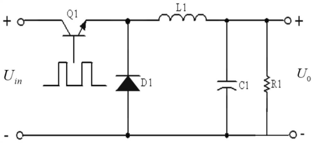
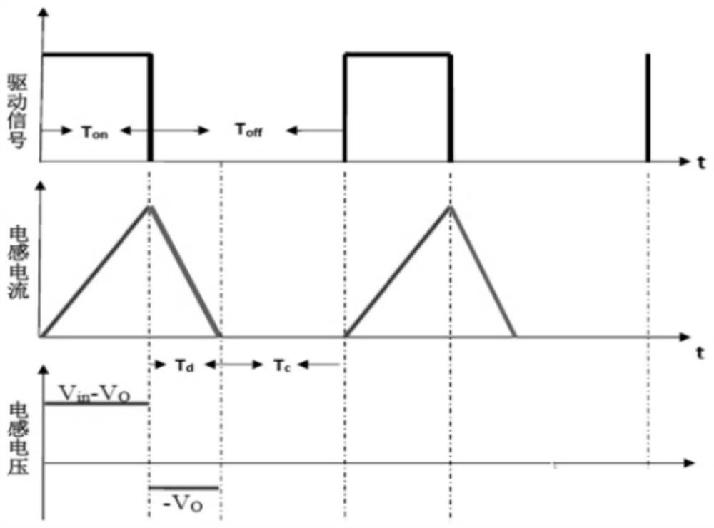
[0024] figure 1 A schematic circuit diagram of the BUCK circuit is shown. When the switch transistor drive signal is high, the switch transistor Q1 is turned on, the energy storage inductor L1 is magnetized, the current flowing t...


PUM


Abstract

The invention is suitable for the technical field of power supplies, and provides a BUCK circuit current calibration method, calibration equipment and a storage medium, and the method comprises the steps: obtaining an input voltage and an output voltage of a BUCK circuit; determining a current compensation coefficient according to the input voltage and the output voltage; and calibrating the output current of the BUCK circuit obtained by sampling according to the current compensation coefficient to obtain a target output current. According to the invention, the current obtained by midpoint sampling is compensated in real time according to the input voltage and the output voltage, so that the current under the full-range voltage is accurate, and constant-current charging can be realized.

Description

technical field [0001] The invention belongs to the technical field of power supply, and in particular relates to a current calibration method of a buck circuit, a calibration device and a storage medium. Background technique [0002] Buck circuits, also known as step-down circuits, are widely used in charging circuits and can be used to charge batteries. figure 1 A schematic circuit diagram of the BUCK circuit is shown. In practical applications, the DMA sampling method or the midpoint sampling method is usually used to sample the output current of the BUCK circuit, and control the output current (charging current) accordingly. Because the DMA sampling method has many sampling points, it will occupy more memory of the controller, and the control is slightly delayed, so the midpoint sampling method is more favored. [0003] However, when the buck circuit needs to be used to charge different batteries, the buck circuit will work in a DCM (Discontinuous Conduction Mode, disc...

Claims


Application Information

Patent Timeline
Patent Type & Authority Applications(China)
IPC IPC(8): H02J7/00H02M3/00H02M3/156
CPCH02J7/00712H02M3/00H02M3/156H02J2207/20Y02B70/10
Inventor 陈青培陈仲清黄詹江勇
Owner ZHANGZHOU KEHUA ELECTRIC TECH CO LTD
Why Eureka
Try Eureka