
Method and system for wirelessly and remotely controlling beacon equipment to generate radio frequency signal

A beacon device and remote control technology, applied in the direction of radio wave measurement system, advanced technology, climate sustainability, etc., can solve the problem that the signal source is not suitable for continuous power-on work for a long time, waste of manpower and material resources, and time-consuming, etc. To shorten the preparation time, avoid miscommunication, and achieve simple results

Pending Publication Date: 2022-06-03
PLA 63698 ARMY +1
View PDF0 Cites 0 Cited by
  • Summary
  • Abstract
  • Description
  • Claims
  • Application Information

AI Technical Summary

Problems solved by technology

[0003] The whole process of tower calibration involves many links such as personnel and vehicles, construction environment, communication and coordination, etc. The organization and implementation is time-consuming and inefficient, and the process needs to be repeated every time tower calibration
For specific applications that require frequent tower calibration, for example, an average of more than 20 times a year, a lot of manpower and material resources are wasted
Moreover, the signal source is not suitable for continuous long-term power-on work as an expensive instrument

Method used


Image

  • Method and system for wirelessly and remotely controlling beacon equipment to generate radio frequency signal
  • Method and system for wirelessly and remotely controlling beacon equipment to generate radio frequency signal
  • Method and system for wirelessly and remotely controlling beacon equipment to generate radio frequency signal

Examples


Embodiment Construction

[0055] In order to be able to understand the above objects, features and advantages of the present invention more clearly, the present invention will be further described in detail below with reference to the accompanying drawings and specific embodiments. It should be noted that the embodiments of the present application and the features in the embodiments may be combined with each other in the case of no conflict.

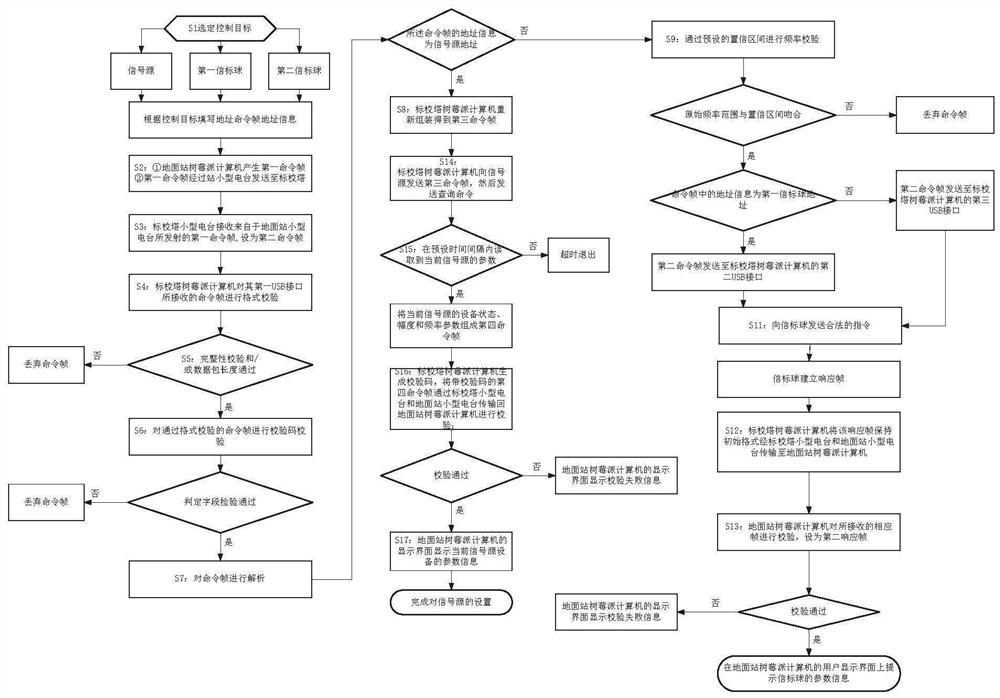
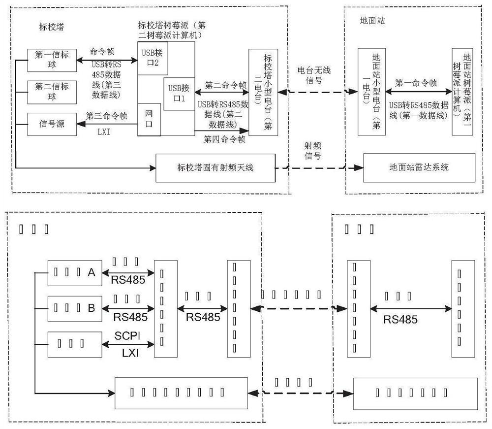
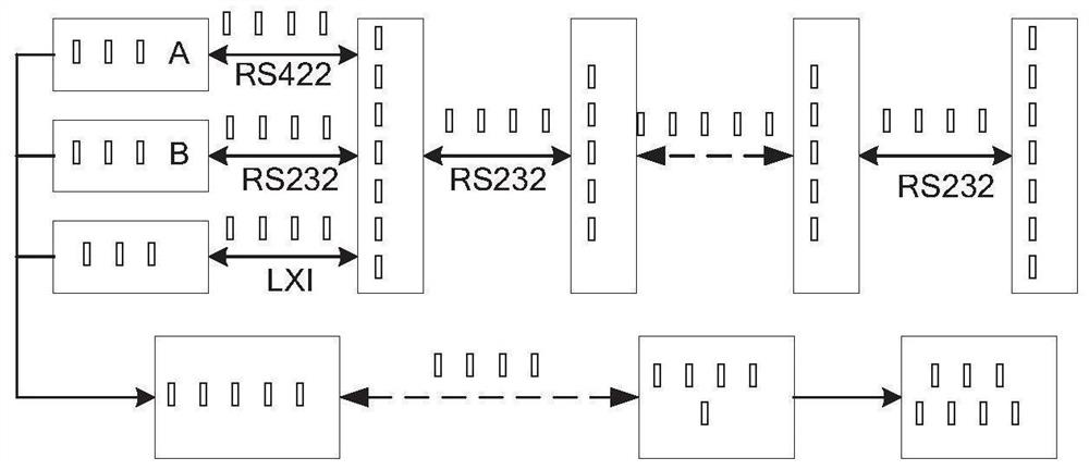
[0056] The present invention will be described in detail below with reference to the accompanying drawings. The wireless remote control beacon device according to the first embodiment of the present invention generates a radio frequency signal system, such as Figure 1 to Figure 5 As shown, it includes a computer, a radio station, and a beacon device; the beacon device includes a signal source, a first beacon ball and a second beacon ball, the first beacon ball generates a 2-4GHz radio frequency signal; the second beacon The ball generates a 22-40GHz radio frequ...


PUM


Abstract

The invention relates to a method and a system for wirelessly and remotely controlling beacon equipment to generate a radio frequency signal. A Raspberry Pi small computer is adopted, the computer is connected with a radio station and a second beacon ball through a first data line, is connected with a first beacon ball through a second data line, and is connected with a signal source through a network cable; the computer edits and generates a control beacon device to modify dot frequency and output a signal instruction, the instruction is wirelessly sent to the calibration tower through the ground station radio station, the calibration tower radio station receives the instruction and transmits the instruction to the computer, and the computer automatically sends the instruction to the signal source, the first beacon ball and / or the second beacon ball after reading the instruction content. And the beacon device generates a required radio frequency signal after executing the instruction, and returns an execution state through the radio station. The tower calibration preparation time of a ground station is remarkably shortened, manpower and material resources are saved, the method has the advantages of being efficient and accurate in control, beacon signals of the signal source and the beacon ball are mutually backed up, and the method is more stable and reliable.

Description

technical field [0001] The present invention relates to the technical field of signal generation, and more particularly, the present invention relates to a method and system for generating radio frequency signals by wireless remote control beacon equipment. Background technique [0002] Calibration of the tower is an important way to calibrate the phase of the radar system and verify the status of the equipment. Under normal circumstances, during the implementation of the tower calibration, the post personnel are required to transport the signal source equipment to the calibration tower 5 kilometers away, go to the top of the tower to manually build the beacon generation environment, and communicate with the ground station by telephone or walkie-talkie. Source turn-on and frequency modification. During manual communication, personnel carry walkie-talkies and signal source equipment to board the calibration tower; when signal parameters need to be changed, ground station per...

Claims


Application Information

Patent Timeline
Patent Type & Authority Applications(China)
IPC IPC(8): G01S7/40
CPCG01S7/40Y02D30/70
Inventor 李俊超马媛媛陈铠邹辉慧范新峰张海龙秦有权陶西贵
Owner PLA 63698 ARMY
Learn More