
Discharging method of parallel energy storage equipment, energy storage inverter and energy storage system

An energy storage device, parallel technology, applied in collectors, secondary battery charging/discharging, irreversible DC power input conversion to AC power output, etc., can solve problems such as reducing battery pack discharge time, and achieve good balanced discharge Effect

Pending Publication Date: 2022-05-31
SHENZHEN POWEROAK NEWENER
View PDF0 Cites 4 Cited by
  • Summary
  • Abstract
  • Description
  • Claims
  • Application Information

AI Technical Summary

Problems solved by technology

The battery pack with the maximum remaining capacity needs to output 1600W. If it exceeds the rated power (maximum output power), the extra 100W has to be shared among the remaining 3 battery packs for output. As much as possible or the remaining power is too small to meet the demand of the 100W, and thus cannot provide normal power supply to the large load, reducing the discharge time of the battery pack

Method used

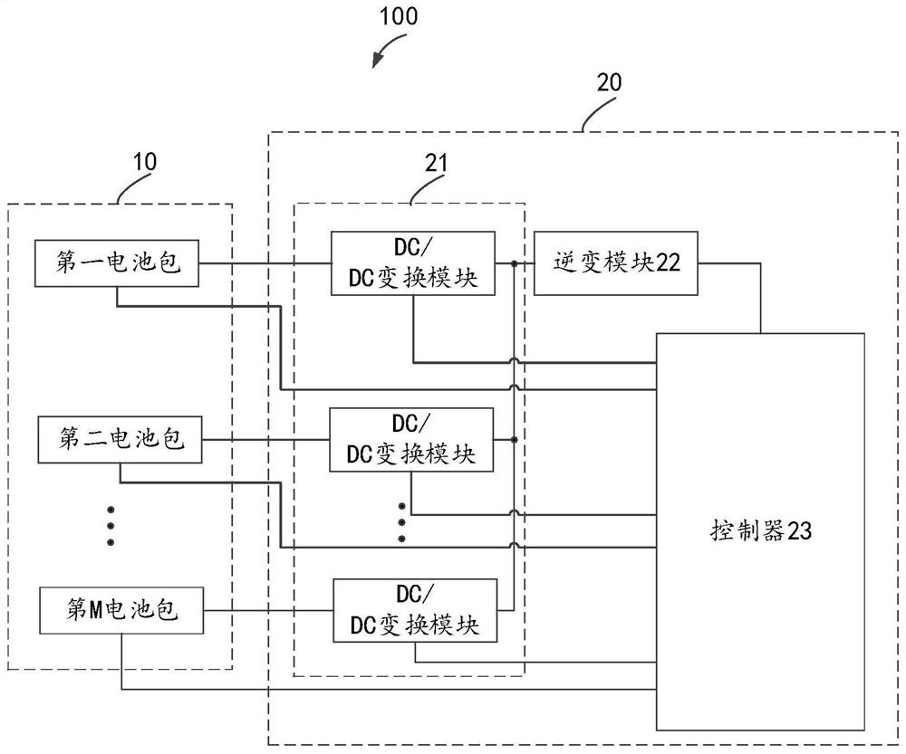
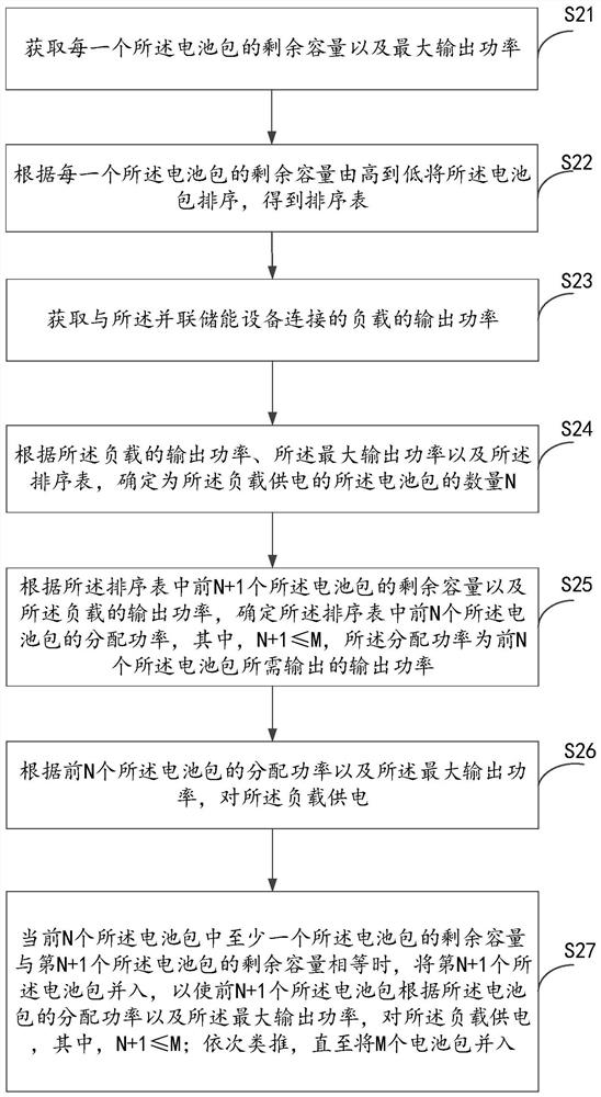
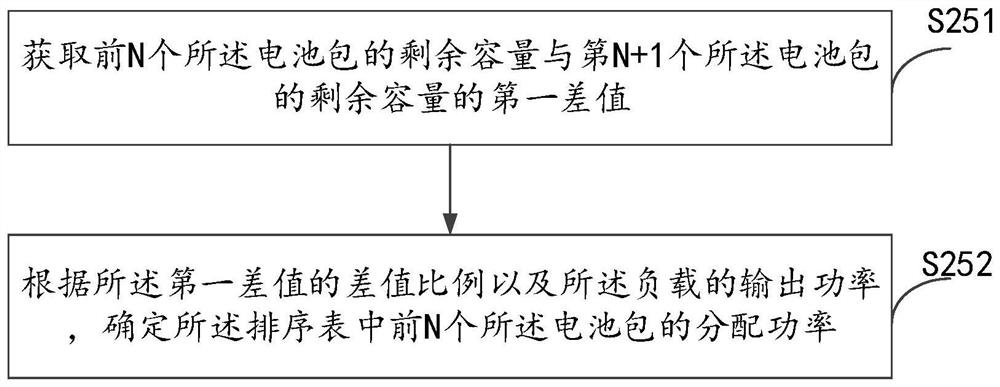

Image

  • Discharging method of parallel energy storage equipment, energy storage inverter and energy storage system
  • Discharging method of parallel energy storage equipment, energy storage inverter and energy storage system
  • Discharging method of parallel energy storage equipment, energy storage inverter and energy storage system

Examples


Embodiment Construction

[0047] In order to make the object, technical solution and advantages of the present invention clearer, the present invention will be further described in detail below in conjunction with the accompanying drawings and embodiments. It should be understood that the specific embodiments described here are only used to explain the present invention, not to limit the present invention. Based on the embodiments of the present invention, all other embodiments obtained by persons of ordinary skill in the art without creative efforts fall within the protection scope of the present invention.

[0048] It should be noted that, if there is no conflict, various features in the embodiments of the present invention may be combined with each other, and all of them are within the protection scope of the present invention. In addition, although the functional modules are divided in the schematic diagram of the device, and the logical order is shown in the flowchart, in some cases, the division ...


PUM


Abstract

The invention relates to a discharging method of parallel energy storage equipment, the energy storage equipment and an energy storage system.The method comprises the steps that firstly, power is supplied to a load through first N battery packs with the high electric quantity, when the residual capacity of at least one battery pack in the current N battery packs is equal to the residual capacity of the (N + 1) th battery pack, the (N + 1) th battery pack is merged into the load, and when the residual capacity of at least one battery pack in the current N battery packs is equal to the residual capacity of the (N + 1) th battery pack; therefore, compared with a discharging method that the M battery packs are directly put into use, the discharging method enables the residual capacity of each battery pack to approach to be equal in the discharging process of the battery packs, that is, the residual capacity of each battery pack is balanced, a better balanced discharging effect is achieved, and if the output power of the load is increased, the output power of the load is increased. The discharging time of the battery pack can be prolonged, and the discharging efficiency of the battery pack is improved. In addition, each battery pack can be independently loaded, so that when a user does not need to adopt a pack combining technology, the electric quantity balance of each battery pack can be ensured, and the use of the user is facilitated.

Description

technical field [0001] The invention relates to the field of energy storage power sources, in particular to a discharge method for parallel energy storage devices, an energy storage inverter and an energy storage system. Background technique [0002] With the improvement of living standards, more and more people are keen on outdoor activities, and energy storage power supplies have become more and more popular in recent years. The demands of users are also gradually increasing. For example, users hope that energy storage devices can carry high-power devices, such as 3000W or 4000W. Generally, each battery pack has a maximum output power, such as 1500W. A single battery pack cannot meet the electricity demand of high-power loads. [0003] In order to realize the loading of high-power equipment, in the existing method, multiple battery packs are usually connected to the host, and the package technology is adopted, and a certain power is output according to the proportion of t...

Claims


Application Information

Patent Timeline
Patent Type & Authority Applications(China)
IPC IPC(8): H02J7/00H01M10/44H02M7/42
CPCH02J7/0063H01M10/44H02M7/42Y02E60/10
Inventor 雷健华秦赓张华唐朝垠
Owner SHENZHEN POWEROAK NEWENER
Learn More